Can you explain what you are trying to do by opening this thread?It is true to say, that to date the only real advancement with LDR design has been marketing of devices containing a potentiometer with a fixed voltage.... that do sell, and people buy in various marketplaces at high prices. There has been no advancement away from nothing more than that marketing, and like a whirlwind of product adoration of a fixed voltage and potentiometer, no one has found time to contribute to any thing else that I am aware of.
You will note I have not mentioned where my product is sold, there has been no image, or website link. I have fully complied with forum rules concerning advertising, and I pay monthly fees for the right to advertise at that different location.
Comments way off focus like I am mining ideas, are totally wrong. I do not copy other persons contributions, and never will.... rather I enjoy finding and creating electronics ideas myself that are different, that perform well and that no one has approached before.
I am proud of the original product I have designed and created, it performs very well as an attenuator, providing excellent audio reproduction 🙂
Cheers / Chris
In your first post
A Light Dependant Resistor LDR is: is a resistor whose resistance decreases with increasing incident light intensity; in other words, it exhibits photoconductivity. It can also be referred to as a photoconductor or CdS device, from "cadmium sulfide," which is the material from which the device is made and that actually exhibits the variation in resistance with light level
A popular circuit for LDR's is to connect them as a L pad attenuator, however all of the Pad forms are readily available to suit LDR's including balanced audio use.
This thread discusses how to go about current control of the anode and cathode terminals of a LDR, a typical device, ( but not limited to ) is the popular Silonex NSL32SR2
The ideal LDR circuit attenuator (a very popular way of using LDR's), would have focus on current being maintained hence controlled whilst a voltage is being varied, as the properties of LDR's ideally suit current control, not voltage control.
A typical attenuator circuit using fixed voltages into potentiometers or any resistance thereafter is a variable ohmic device and therefore has preference altering current straight away before voltage, Such circuits dismiss or abandon current control. This thread will attempt a difficult subject, circuits that do the opposite. That is to have preference or some ability at least, of current control of the anode and cathode terminals.🙂
Throughout the thread, you avoid any detailed circuit discussions, you do not do SPICE simulations, the only measurements you took seemed only measurements at one single position which showed the channel balance is much worse than a normal 1$pot.
I think if you like to hustle some money, DIY is probably not the place to do it. I had listened to a Korean made LDR volume control that contained fully matched channels, full remote control, even a display with volume setting. The only thing it did not have was a nice chassis.
I cannot say how it sounds, but just the fact that it uses LDR will make it better regardless how it is controlled. I think you really need to do some more humbling work before you start trying to pull buyers. I can identify some places where you were actually asking about "what people want". It is not bad, but you have to have some knowledge to back up your claims.
Last edited:
Can you explain what you are trying to do by opening this thread?
Hi soongsc
Discuss and contribute to ideas, people may have concerning trying to achieve better if at all possible control of LDR devices such as the popular NSL32SR2
from Post 1
"A typical attenuator circuit using fixed voltages into potentiometers or any resistance thereafter is a variable ohmic device and therefore has preference altering current straight away before voltage, Such circuits dismiss or abandon current control. This thread will attempt a difficult subject, circuits that do the opposite. That is to have preference or some ability at least, of current control of the anode and cathode terminals "
Cheers / Chris
First of all, this statement from post one is not true. There have been VCC controlled devices mentioned, I even bought a kit.Hi soongsc
Discuss and contribute to ideas, people may have concerning trying to achieve better if at all possible control of LDR devices such as the popular NSL32SR2
from Post 1
"A typical attenuator circuit using fixed voltages into potentiometers or any resistance thereafter is a variable ohmic device and therefore has preference altering current straight away before voltage, Such circuits dismiss or abandon current control. This thread will attempt a difficult subject, circuits that do the opposite. That is to have preference or some ability at least, of current control of the anode and cathode terminals "
Cheers / Chris
Second, why can you not explain why your circuit is supposed to accomplish this? The way you are handling this is like some technicians of 30 years ago in Taiwan that have no knowledge on how things work, they manage to hit a sweet spot by fumbling around, and rave about it, defend it, ... in a forum discussion here, you really have to have some solid knowledge otherwise you break your reputation. If you don't want to reveal the knowledge, then you should have measurements to back up your claims.
Last edited:
It is true to say, that to date the only real advancement with LDR design has been marketing of devices containing a potentiometer with a fixed voltage.... that do sell, and people buy in various marketplaces at high prices. There has been no advancement away from nothing more than that marketing, and like a whirlwind of product adoration of a fixed voltage and potentiometer, no one has found time to contribute to any thing else that I am aware of.
OK, that's a marketing goal, product differentiation, but what specific technical issues that are problems in current designs are you trying to address? Can you show how your solution addresses these, with actual data to back this up? You are, after all, selling this stuff and posting in a noncommercial part of the forum.
Hi soongscFirst of all, this statement from post one is not true. There have been VCC controlled devices mentioned, I even bought a kit.
Did you build it from that kit ? Well did it work any better, or sound any better, than a voltage controlled device.
Second, why can you not explain why your circuit is supposed to accomplish this? The way you are handling this is like some technicians of 30 years ago in Taiwan that have no knowledge on how things work, they manage to hit a sweet spot by fumbling around, and rave about it, defend it, ... in a forum discussion here, you really have to have some solid knowledge otherwise you break your reputation. If you don't want to reveal the knowledge, then you should have measurements to back up your claims.
The use of an op amp that is single ended, has a feedback path and is capable of delivering current and voltage accessed from its input. noting high impedance of that load away from its source, is a good starting point. So, perhaps we start here.
measuring voltage and current of a TL072,... and see if a load is possible connected to an inverting input,, and suggest or dismiss, having an LDR connected from that point.
.
If such an idea is accepted, then I can provide that either diodes or transistors saturated as diodes, are needed to current steer to the LDR devices...
However i think also a fixed voltage pot connected model should be also measured... to compare any differences ... to then eventually translate this to better audio reproduction, one vs the other, maybe voltage is better, maybe some current control is better.
end result is trying to nut out better use of LDR's relative to audio reproduction. 🙂
Cheers / Chris
Last edited:
The use of an op amp that is single ended, has a feedback path and is capable of delivering current and voltage accessed from its input. noting high impedance of that load away from its source, is a good starting point. So, perhaps we start here.
measuring voltage and current of a TL072,... and see if a load is possible connected to an inverting input,, and suggest or dismiss, having an LDR connected from that point.
.
If such an idea is accepted...
Good starting point for what? You're still not saying what problem you're trying to fix nor showing any data that your $450 solution fixes that problem.
OK, that's a marketing goal, product differentiation, but what specific technical issues that are problems in current designs are you trying to address? Can you show how your solution addresses these, with actual data to back this up? You are, after all, selling this stuff and posting in a noncommercial part of the forum.
Yes, I am trying to address that depleting current through a pot then maybe also depletes or lessens the ability of the LDR to work properly relative to audio reproduction. Is it possible that current control is the better way of doing this ?
My solution addresses this by maintaining voltage to 1.4v and current to .054ma even when the device is at maximum attenuation. This says to me how can a LDR receive voltage and current and still work to attenuate.... so maybe .054ma and 1.4v or close to it is the very starting point for LDR's, or is something else enabling it to have signal side zero or extremely close to silence.
Cheers / Chris
The LDR is still being studied. Since I have at least two kits, I hate to make any claims without data to back it up. We did consider using a microprocessor to conduct active measurement then store the curves in memory. Since there were some other features that were planed for the whole project, the person working on it could not grasp the idea and did not have enough experience to carry on. So the idea is currently on hold.Hi soongsc
Did you build it from that kit ? Well did it work any better, or sound any better, than a voltage controlled device.
The use of an op amp that is single ended, has a feedback path and is capable of delivering current and voltage accessed from its input. noting high impedance of that load away from its source, is a good starting point. So, perhaps we start here.
measuring voltage and current of a TL072,... and see if a load is possible connected to an inverting input,, and suggest or dismiss, having an LDR connected from that point.
.
If such an idea is accepted, then I can provide that either diodes or transistors saturated as diodes, are needed to current steer to the LDR devices...
However i think also a fixed voltage pot connected model should be also measured... to compare any differences ... to then eventually translate this to better audio reproduction, one vs the other, maybe voltage is better, maybe some current control is better.
end result is trying to nut out better use of LDR's relative to audio reproduction. 🙂
Cheers / Chris
I think the LDR volume control is a nice concept, but bear in mind, if the other parts of the audio system is not up to par, it makes no sense to let this thing reveal the bad performance from other parts in the audio playback chain. This is no magical thing, and really should not be portrayed as such.
Now, if you claim that your design will eliminate the need for matching the LDRs, you either need measured data to show it, or you have to have full explanation from the LDR performance point of view that your design solved this. I believe the factory sorted devices are within 20% tolerance based on steady current supply. Why would your design improve on this?
Last edited:
Good starting point for what? You're still not saying what problem you're trying to fix nor showing any data that your $450 solution fixes that problem.
If we rely on Ohms law V =5v, is divided by 20K how much current ? = .025ma can an LDR device such as NSL 32SR2 work in an audio L pad circuit with that very wee amount of current.
I consider its all over rover, its off and is doing flat zero nothing. many of you have such circuits, what voltage do you get when pot is at 20k. ?if it is less, would indicate current is even smaller still. If LDR is doing nothing then maybe this relates to the signal side audio reproduction as well by making resistance very high and maybe too it is not as good at
L/R balance.
As I have demonstrated my circuit even at 50k is not only providing voltage at 1.4v measured at the anode and cathode, but it is also providing current of .054ma.... I think there is advantage in that. Perhaps a letter to Silonex may confirm. 🙂
Cheers / Chris
Your circuit is very confusing, it seems you are adding a current bias to the resistive element? If you are maintaining 0.054ma on the LED side, how can you change volume? The current has to change for the resistance value to change.Yes, I am trying to address that depleting current through a pot then maybe also depletes or lessens the ability of the LDR to work properly relative to audio reproduction. Is it possible that current control is the better way of doing this ?
My solution addresses this by maintaining voltage to 1.4v and current to .054ma even when the device is at maximum attenuation. This says to me how can a LDR receive voltage and current and still work to attenuate.... so maybe .054ma and 1.4v or close to it is the very starting point for LDR's, or is something else enabling it to have signal side zero or extremely close to silence.
Cheers / Chris
Your circuit is very confusing, it seems you are adding a current bias to the resistive element? If you are maintaining 0.054ma on the LED side, how can you change volume? The current has to change for the resistance value to change.
Yes a current bias sufficient for 2x LDR at any given time is provided to the resistive element, but if we go back to TLO72 providing or giving up voltage at its inverting input if the positive input is grounded, and accepting voltage from its feedback path via that resistive element, we then start to see maintenance of current that is otherwise unavailable in other implementations is available due to voltage always being present.
Yes the changing volume bit is quite charming, my thoughts are that it is the nature of the op amp when placed with inversion to process gain where relationship R2/R1 is provided.
however i believe due to no R2 resistor being present that the LDR devices then become R2.
Here is what happens if we deploy resistors from inverting input upper point to ground, You get a log curve ..between 22k and 18k is good. resulting in volume that is less apparent at lower settings. The current steering diodes are preferred however with 3x on upper and 3x on lower get the circuit to a point where pleasant volume is achieved anyway... and stereo balance improves to a point that says thats nearly as good as you can get.
If we introduce resistance on Lower inverting input to gnd we get a higher volume.
Cheers / Chris
Try again. 5V divided by 20K = 0.25mA. Ten times higher than you thought.If we rely on Ohms law V =5v, is divided by 20K how much current ? = .025ma can an LDR device such as NSL 32SR2 work in an audio L pad circuit with that very wee amount of current.
Advantage in what? Using less current?As I have demonstrated my circuit even at 50k is not only providing voltage at 1.4v measured at the anode and cathode, but it is also providing current of .054ma.... I think there is advantage in that.
I think your schematic really has to be completed before any discussion can go on. What you are saying makes no sense. Supplying current to the LED side of the LDR and supplying current to the resistive element are two separate issues. The LDR relationship with it's current to the LED side is a log curve, you need nothing else to make it so.Yes a current bias sufficient for 2x LDR at any given time is provided to the resistive element, but if we go back to TLO72 providing or giving up voltage at its inverting input if the positive input is grounded, and accepting voltage from its feedback path via that resistive element, we then start to see maintenance of current that is otherwise unavailable in other implementations is available due to voltage always being present.
Yes the changing volume bit is quite charming, my thoughts are that it is the nature of the op amp when placed with inversion to process gain where relationship R2/R1 is provided.
however i believe due to no R2 resistor being present that the LDR devices then become R2.
Here is what happens if we deploy resistors from inverting input upper point to ground, You get a log curve ..between 22k and 18k is good. resulting in volume that is less apparent at lower settings. The current steering diodes are preferred however with 3x on upper and 3x on lower get the circuit to a point where pleasant volume is achieved anyway... and stereo balance improves to a point that says thats nearly as good as you can get.
If we introduce resistance on Lower inverting input to gnd we get a higher volume.
Cheers / Chris
I think your schematic really has to be completed before any discussion can go on. What you are saying makes no sense. Supplying current to the LED side of the LDR and supplying current to the resistive element are two separate issues. The LDR relationship with it's current to the LED side is a log curve, you need nothing else to make it so.
My reference to resistance is from inverting input of op amp to ground I only supply current and voltage to the LED anode and cathode. I do not supply current or voltage to the resistive element, other than signal from CD player or other .🙂
Then if this is constant current, as you described, the resistance value of the LDR cannot change, thus no volume control.My reference to resistance is from inverting input of op amp to ground I only supply current and voltage to the LED anode and cathode. I do not supply current or voltage to the resistive element, other than signal from CD player or other .🙂
Yes, I am trying to address that depleting current through a pot then maybe also depletes or lessens the ability of the LDR to work properly relative to audio reproduction. Is it possible that current control is the better way of doing this ?
My solution addresses this by maintaining voltage to 1.4v and current to .054ma even when the device is at maximum attenuation. This says to me how can a LDR receive voltage and current and still work to attenuate.... so maybe .054ma and 1.4v or close to it is the very starting point for LDR's, or is something else enabling it to have signal side zero or extremely close to silence.
Cheers / Chris
I hate to have to be the one to break this to you, Chris, but voltage and current are not independent of each other. There's an enormous body of work (work, not just hand-waving and talking) called Physics, where (along with many other things) the laws of electricity have been discovered and studied. You should check it out, sometime. Lots of new buzzwords for you. And Physics is only one part of this even larger body of fields of work, called Science. There's even a whole method named after it. Pretty impressive, I'd say.
So, if electric current is like water moving in a waterpipe, then voltage is like the water pressure. There can be no current without voltage, just like water won't flow in a pipe without pressure. But there can be voltage with no current, just like when a valve is turned off, so no water flows, but the pressure is still there, so that if the valve is opened the water will immediately flow again. But if you think about it, pressure is relative, because if you had two tanks connected by a pipe, even if one tank had 1000 psi of pressure, no water would flow if the other tank also had 1000 psi of pressure.
Your ideas so far are all wet. As a bagpipe maker once said to me, "Electricity is nice but don't get any on you.".
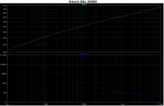
It turns out that, according to Silonex's data, the 1.4 Volts that you keep quoting is just about the lowest-possible voltage that the NSL-32SR2's LED can have, if even one one-millionth of an amp is flowing through it. And at that point the CdS cell (LDR portion) would have a resistance of almost half a million Ohms. I'm not sure where you got the .054 mA that you also keep quoting but with that current through the LED the LDR would be at about 2.2k Ohms (2200 Ohms), in a typical Silonex device. However, at that point, the voltage across the LED would have to be about 2.15 Volts.
I'm attaching two plots, which were generated with my LT-Spice simulation model of the NSL-32SR2. But the model consists of data from the Silonex datasheet. Anyway, the bottom plot shows the resistance of the LDR on the vertical scale, which results from the LED current on the bottom horizontal scale. The top plot shows the voltage across the LED, which results from the current through the LED.
NOTE that this is also how the Lightspeed attenuator works. It uses current control! (Remembering from the water pressure lesson above: ) The potentiometer divides the supply voltage, and is merely a convenient (and clever) way to get the series and shunt LED-current control voltages to vary inversely (one getting smaller as the other gets larger.). So we now have a control voltage for each LED's current. There is one other very important component in each LED's circuit loop and that's the current-limiting resistor. The current we make is going to go through the LED, no matter what, because our control voltage is larger than the voltage the LED can get across it. If the LED wasn't there, then the current around the loop would be determined only by the resistor and the voltage provided as the pot changed position. So we could ramp the current up and down by changing the pot voltage. And the lowest and highest values of the current's amplitude are determined by the reistor's value and the lowest and highest voltages that are provided. Mentally adding the LED back into the circuit still leaves us with a controllable range of current. It's just a little different, and no longer quite linear, because the LED gets a voltage induced across it by the current (but with a changing proportionality factor, i.e. non-linearly), and that LED voltage changes the relative voltage across the resistor, changing the current ramp's shape from what it would have been without the LED in there. But it's not enough to stop the show and we still get some range of current that we can ramp through, up and down, under the control of the pot.
So, we study the plots and decide what range of current we can use, based on what LDR resistances we need in order to get a reasonable range of attenuation, with reasonable input and output restistances for the attenuator so it can operate well-enough with a large-enough range of sources and loads. And we decide on a power supply voltage and a current-limiting resistance (and power rating) and a pot value (and power rating) based on how much current we need, what voltage might be convenient, what VA rating we can get away with for the power supply, and whether or not the power dissipation in the pot or the current-limiting resistor or the power supply might be excessive, or if something might be in an inconvenient range.
I'm wondering if you read all of that and tried to understand it or just skipped to the end.
Attachments
Last edited:
Since LT SPICE is brought up, I wonder whether it is possible to show the phase, group delay, etc. information through the user interface? I like that capability in ORCAD
Then if this is constant current, as you described, the resistance value of the LDR cannot change, thus no volume control.
Hi soongsc
As you can see from earlier posts current indeed changes ranging from .054ma at 1.4v to 1.7v at 21ma on one pair the upper, the other pair the lower set has more initial current .126ma and slightly higher voltage starting at 1.45v and up to 1.75v at 15.4ma, note voltage remains active. only altering .350v and current changes.
What is needed is a graph showing 1/V for a voltage driven ldr, and I/V for the circuit I have drafted measured at anode and cathode. This I think will give indication of difference
of design approach at least one circuit vs the other.... but assessing that difference in terms of available data about NSL32SR2 might give some answers.. and sound differences resulting, is of course subjective.
All the models I am building with matched LDR's from earlier schematic, sound the same, offering excellent L/R channel balance....
Sorry I am reluctant to post any further schematics,until things calm down, with normal discussion....
Cheers / Chris
This is my normal discussion mode. I think of course there are things that can be improved in any design. But if you want to do it in an open forum, make claims of superiority, but publish incomplete schematics, and hope to generate massive massive discussion to get people to do more work than you have done, this is really the wrong place.
Generally people first post complete schematics if they want other people to try and comment. Then based on various experience, the discussion evolves. Lots of threads here evolve very nicely. At least the schematics should allow people to compare your explanation to fully understand what you are trying to say so that effective communication can take place.
Generally people first post complete schematics if they want other people to try and comment. Then based on various experience, the discussion evolves. Lots of threads here evolve very nicely. At least the schematics should allow people to compare your explanation to fully understand what you are trying to say so that effective communication can take place.
Last edited:
Hi Tom
Yes I read all of your posts, and will continue to do so, I understand the relationship of voltage to resistance resulting in variance of current, ie V/R =I and I never tire from enjoying the basics, and I think neither do you.
My circuit performs also with this inverse relationship to the LDR's using a single pot, rather than a dual
The starting point vs resistance plots, you kindly provide now give some comparison for me to compare my design with. Graph plots is where I am at presently. I am going to record a video of current change, using a 10 - 20 second grab to greatly assist production of a graph and a video of voltage at the same time, my other DMM a Fluke doesn't auto range so I am going to have to work with that, by stopping at each increment..
I will need to do anode of top LED and anode of bottom LED which should show LED characteristics. To show signal side resistance as well varying might also be possible as the DMM that does not auto range provides a stop and start point enabling to show where resistance is varied within that individual range.
Cheers / Chris 🙂
Last edited:
- Status
- Not open for further replies.
- Home
- Source & Line
- Analog Line Level
- Light Dependant Resistor Current Control