Did you get a chance to try that NFB cap size test? The difference should be fairly obvious.
Trick:
If, perchance, you like the lower clearer bass but didn't like something else about it, then it is possible to ask the amp to pass the mids and treble through the 22u, then pass the bass through the 330u. This is easy. You'd put a 3.3R or 3.9R series to the groundside pin of 330u, causing it to be slightly less efficient. The 22u will play as it did before you added the 330u. . . except for bass pitches that the 22u can't pass, and that is when the 330u would pipe up.
P.S.
If the speakers are out of commission, you might want to build that Rod Elliot headphone adapter for testing. If the unit really is for testing, capacitor couple (block dc at) headphone ground and make the adapter monophonic so you can test one amp at a time.
I've been in the attic and recovered my second Akai speaker. Plugged it up and had a good listen to various tracks.
Now As I only have one channel up and running I am only getting 50% of the overall performance. I still sat there my mouth alternating between a crazed smile and slack jawed astonishment.
Now a confession. The other speaker where the rubber edge has disintegrated - Also produced lots of smoke during the 'silliness' of first failed attachment issues. So I think the main woofer is probably toast. If the tweeter and mid survived I may well batter the both cases to death to retrieve both sets for 'future projects'.
I think I will need a small pre-amp just to lift the possible audio sources outputs, as you suggested, as at low to mid volume some of the detail was lacking in the tracks I was listening to. At about 75% - 100% detail was spot on! I swear I could hear the sound engineer breaking wind in the back ground on one track 😀
EDIT: Just caught your post Daniel. I haven't yet. I will get the other Amp up and running and when I have both mounted on a testbed I will have a bash with the 'tweaking'. So much fun to be had!
regards
Foo.. Currently raiding Ebay for 12mm Ply!
Last edited:
. . .So I think the main woofer is probably toast. If the tweeter and mid survived I may well batter the both cases to death to retrieve both sets for 'future projects'.
This is specifically the case for woofer replacement. You may also need to replace any caps that are parallel to the woofer. For woofer replacement, you try to find similar efficiency and "wants same size box" and then fine tuning adjustments are minor or at least doable in short order. I can see that you need a good set of test speakers, so it seems good to repair them. The retail cabinets can be brought close to handmade performance by simply adding braces. A major advantage is that this prospect is both low cost and speedy. And, it doesn't prevent you from building more speakers later.
I think I will need a small pre-amp just to lift the possible audio sources outputs, as you suggested, as at low to mid volume some of the detail was lacking in the tracks I was listening to. At about 75% - 100% detail was spot on! I swear I could hear the sound engineer breaking wind in the back ground on one track 😀
The highly adjustable MooseFet project is fun to use and it is very adjustable for harmonics. It can be started out with IRF510 for a sort of russian tube sound, or start out with the more neutral (lower distortion) choice with IRF710. Of course there are many preamp projects available and the Decibel Dungeon NE5532 is a particularly easy and yet excellent performer.
There may be a different artifact at play, like this: "Only sounds good loud" is usually impedance mismatch. The most frequent cure for that one, especially with computer source, is increasing the amplifier's input load. I cannot remember which side of the potentiometer to put additional load resistors, but it should take only minutes to find out.
I have done one tweak. I have turned the regulator up to +/- 35VDC. Why not. It's there so I may as well use it.
We have two problems there. Which problem you get depends on which speaker you use.
4 ohm speaker:
For regulated rails, operation at voltage higher than 31vdc rails becomes dramatically less safe.
For unregulated rails, 31vdc would be your max "fully loaded" high current voltage pulldown figure, albeit the unloaded figure may be slightly higher.
These are push for power numbers, not safe operating area. 35vdc is much worse.
8 ohm speaker:
To decrease occurrence of spike system counterproductive clipping performance, we usually max the voltage for spike system chips, but we've come up a bit short for 8 ohm speakers.
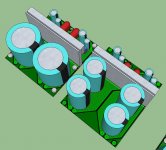
It is unorthodox to charge PAIRS of 10,000uF caps while simultaneously powering four regulators and two amplifiers. This is a request for pulldown. It also pushes the little rectifiers into their more dramatic voltage drop region during the extra slow charge of longer duration because of the timer function of the overlarge caps.
You need a pair of KBPC3501 (bolted to chassis, not boards) with a pair of 2,200uF directly soldered to each of the rectifiers. And you need to replace the 10,000uF caps at your reg boards with something that can be fully charged a lot faster, and that means smaller caps, such as 2,200uF or 1,000uF.
We can charge 8,800uF or 6,400uF a lot faster than 20,000uF and the duration of pulldown can decrease by same proportion.
The interlink cable (four 16ga for voltage and 1 12ga for Earth/Chassis ground--there is 5 wires) between the two enclosures now carries clean DC.
This new arrangement now allows the regulator boards to go in the amp box where they should be, since the cable between reg and amp is supposed to be ~1cm if you want to enforce a flat response.
Check transformer datasheet pulldown figure. After the redo for less sag and faster charge, we may be able to do 36.5vdc to 37vdc rails when also using 8 ohm speakers.
The less sag, faster charge, unreg section upgrade will be more predictable.
For 8 ohm speakers you don't have to make any change, but slower charge bigger pulldown limits reg sections to about 35vdc.
-------------------
next up, grounding
Just bear in mind that you DO have monobloc amplifiers, even if you happen to put them in a single box. In this case, you do have two zero volt taps--they are the speaker negatives. For the left channel, connect a ground loop breaker circuit from speaker negative to earthed chassis ground. Do an identical copy of that for the right channel.
Hand match the resistors via digital ohmmeter for left and right ground loop breaker circuits of monobloc amplifiers.
And
Hand match the resistors via digital ohmmeter for left and right small signal groundlift resistors of monobloc amplifiers.
and
Remember, your wiring is the same as regulated monobloc.
For a stereo amp, the grounds meet only once; but for a monobloc, the grounds of left and right never meet except for loops breakers resistors at larges signals and groundlifts resistors at smalls signals The totally individualized circuits are what gives the monobloc/dual-mono amplifiers wider sounds.
Last edited:
Hi Daniel
Thank you for the information. I rather thought that the current 4ohm was pushing it a bit. Luckily my working Akai is 8ohm.
I do understand your premise for more lower value caps to aid faster support of the rails to prevent sag and I will look up some replacements that I can replace the 10,000uF's with to aid this.
I am looking at, again, a single enclosure for everything which will shorten the power interlinks.
I will be using a pair of safety disconnects with the unit and will be re-reading how to wire everything up with proper reference to power and audio grounds.
This is great stuff! I just wish I had a pair of speakers to get the full effect!
regards
Foo
Basically: Pushed specs is not an especially pretty place to be, so dial the rails down a bit prior to performing any audio fine tuning. If either audio amp or regulator exceeds margin, either or both will add noise.
EDIT:
The output of the rectifiers need caps and the input of the regs need caps and the interlink cable goes between, just like CRC except that the "R" in this case is a cable.
EDIT:
The output of the rectifiers need caps and the input of the regs need caps and the interlink cable goes between, just like CRC except that the "R" in this case is a cable.
Last edited:
See the datasheets for KPBC1004's and compare to KBPC3501's for the voltage versus current charts. The better option(s) for you has the voltage drop expressed like wall, straight up, minimum sag. That is KBPC3501's
400v diodes sag more than 100v diodes.
10a diodes sag more (sooner) than 35v diodes.
Combining both minimum sag features is then KPBC3501's per each secondary. The performance of KBPC2501's or KBPC3502's is almost as good.
A rectifier upgrade will help give you a slightly more comfortable margin. . . or at least not suddenly sag at the worst possible time for it. Please do see the charts.
P.S.
Also for minimum sag (really fast charge), directly attached caps is fastest, and when you do that, you also bolt the rectifiers to the chassis to help keep them and their caps cool. Conveniently, this doesn't need a board.
Hi Daniel
Everything duly noted. I now have a new PCB pattern drawn up for the regulator. It is set to take two pair of 2200uF or two pair of 4700uF.
At this juncture, other than finishing the current sets, I will be going for a second build to apply all the changes and improvements with the new PCB patterns. I may even stretch to a pair of toroids to run the future unit at 'maximum' efficiency.
regards
Foo
Attachments
Since you have 4 reg boards, you could just replace the the 10,000uF with 2,200uF on the boards that you already have (simply 1 new drilling per board will adapt the pin spacing without making new boards).
Just don't forget to put 1 pair 2,200uF direct to each Rectifier. That is what allows your cabling to work out right--super short between amp and reg boards, and as long as you need between Rectifier and reg boards.
Count it up:
4,400uF at V+ rectifier
. . . and then cables. . .
2,200uF at V+ reg for left channel
2,200uF at V+ reg for right channel
4,400uF at V- rectifier
. . . and then cables. . .
2,200uF at V- reg for left channel
2,200uF at V- reg for right channel
That is 8,800uF per each rail, it is fast, and it is plenty.
I'm not so concerned about the 10,000uF caps (except for the lack of caps at/onto the rectifiers) but the little rectifiers do bother me a bit. Nearly triple the load on those little guys causes voltage drop (diode drop curve) that we didn't want.
Hi Daniel.
Thanks for the heads up. I have located the new bridge rectifier at one of my 'usual' suppliers and as and when funds allow I will get these.
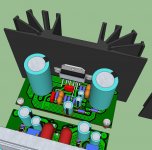
The 'significant other' having stepped out of the house the other day allowed me to 'crank the volume up' on the amp.
Initially I was a bit worried by the harsh treble but this turned out to be the equaliser being turned on. Once turned off I was treated to some delightful sounds.
This also pushed the amp and regulator and they warmed up and performed well. The new rectifiers/caps and regulator caps can only improve things I'm sure.
regards
Foo
Thanks for the heads up. I have located the new bridge rectifier at one of my 'usual' suppliers and as and when funds allow I will get these.
The 'significant other' having stepped out of the house the other day allowed me to 'crank the volume up' on the amp.
Initially I was a bit worried by the harsh treble but this turned out to be the equaliser being turned on. Once turned off I was treated to some delightful sounds.
This also pushed the amp and regulator and they warmed up and performed well. The new rectifiers/caps and regulator caps can only improve things I'm sure.
regards
Foo
Rectifiers:Hi Daniel. Thanks for the heads up. I have located the new bridge rectifier at one of my 'usual' suppliers and as and when funds allow I will get these. The 'significant other' having stepped out of the house the other day allowed me to 'crank the volume up' on the amp. Initially I was a bit worried by the harsh treble but this turned out to be the equaliser being turned on. Once turned off I was treated to some delightful sounds. This also pushed the amp and regulator and they warmed up and performed well. The new rectifiers/caps and regulator caps can only improve things I'm sure.
regards
Foo
On that list, improvements probably come from 2 sturdy rectifiers and pairs of 2,200uF caps directly upon each of the rectifiers.
Reg boards:
Subjective sound quality versus faster charge--those are such different things.
I am not sure if changing the 10,000uF to smaller would make an improvement or dis-improvement, so do only one channel (leave one channel un-altered) and a-b compare to find out.
Input:
If 2 amplifiers with one speaker, you can use a little dpdt switch (this amp or that amp) for a-b comparisons.
Hello there
Slow progress at the moment. Money is short, as ever, so I am biding my time.
I had enquired in another sub section about using a pair of bass woofers as part of my set up but I think the mismatch is too great, what with them being aimed at car use. So I am thinking of selling them on ebay to raise a bit of cash to further progress.
I have also found rubber surrounds on the 'Bay of E' with a view to fixing my Akai woofers. I have tested the one that smoked and it seems to be OK with regards to impedance and actual function.
Having dropped the cover off the one I had been using the rubber has, not surprisingly, also disintegrated.
Other than that, lack of funds not with standing, I could replace the pair and fit the replacements into the existing cabinets just so I have a working test set.
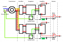
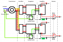
I have been running over the basic wiring of the dual mono set up and have knocked up the attached drawing. Is it correct? Assume the 240VAC Supply is socketed, switched and fused.
Other than the main AC switch on the mains I am looking at using a 'soft touch' button to switch the unit on and off. That is a set of relays which toggle on/off at the touch of a single button. My question here is where to splice in the relays. Between Rectifier and Regulator or between Regulator and Amplifier? I am assuming I'll need to switch the +VE and -VE if switching is done between the Regulator and Amplifier. Or is switching the +VeE line between Rectifier and Regulator?
regards
Foo
Slow progress at the moment. Money is short, as ever, so I am biding my time.
I had enquired in another sub section about using a pair of bass woofers as part of my set up but I think the mismatch is too great, what with them being aimed at car use. So I am thinking of selling them on ebay to raise a bit of cash to further progress.
I have also found rubber surrounds on the 'Bay of E' with a view to fixing my Akai woofers. I have tested the one that smoked and it seems to be OK with regards to impedance and actual function.
Having dropped the cover off the one I had been using the rubber has, not surprisingly, also disintegrated.
Other than that, lack of funds not with standing, I could replace the pair and fit the replacements into the existing cabinets just so I have a working test set.
I have been running over the basic wiring of the dual mono set up and have knocked up the attached drawing. Is it correct? Assume the 240VAC Supply is socketed, switched and fused.
Other than the main AC switch on the mains I am looking at using a 'soft touch' button to switch the unit on and off. That is a set of relays which toggle on/off at the touch of a single button. My question here is where to splice in the relays. Between Rectifier and Regulator or between Regulator and Amplifier? I am assuming I'll need to switch the +VE and -VE if switching is done between the Regulator and Amplifier. Or is switching the +VeE line between Rectifier and Regulator?
regards
Foo
Attachments
Surround replacement is a preferred fix. The puff of smoke could have been a crossover capacitor, an elderly low voltage electrolytic. Nichicon ES 50v is a an economical high performance replacement for midrange and tweeter use. For woofer use, the 100v models are a bit more sturdy. Also measure/inspect any resistors that are in the crossover.I have also found rubber surrounds on the 'Bay of E' with a view to fixing my Akai woofers. I have tested the one that smoked and it seems to be OK with regards to impedance and actual function.
That mess would increase your electricity bill while also dramatically decreasing longevity. Instead of that problem, I would prefer a nice mechanical switch for transformer primary, so that off means off. If you desire automation, buy either a "smart stick" auto switching power strip or a remote control kit.Other than the main AC switch on the mains I am looking at using a 'soft touch' button to switch the unit on and off. That is a set of relays which toggle on/off at the touch of a single button. My question here is where to splice in the relays. Between Rectifier and Regulator or between Regulator and Amplifier? I am assuming I'll need to switch the +VE and -VE if switching is done between the Regulator and Amplifier. Or is switching the +VeE line between Rectifier and Regulator
Hello there
The crossover is fine, double checked, the smoke was definately the driver. Both drivers have been cleaned of the remnants of old surrounds and a pair of large subwoofer (Car type) are now on Ebay in a hope to raise funds for the new surrounds and parts towards the ongoing project.
I agree that I was looking at one unholy mess of switching 😀 So that idea has been sent to the burner!
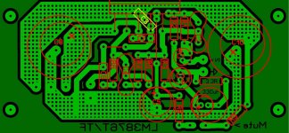
The 'MKII' PCB has been fettled a bit more. The PCB is a little bit deeper allowing the mute pads new position. This in turn makes room for the extra cap and series resistor, as you suggested, for 'enhanced bass ability'. Also extra pads have been added to allow the fitting, track side, of a parallel cap to C1, again an early suggestion by yourself, to allow some experimentation.
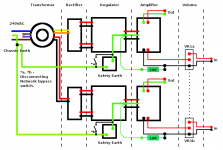
To the diagram of the 'basic wiring' I have added a 'ground lift switch' to the safety earth, a suggestion of Andrew's. I am assuming I have all the wiring arranged correctly??
regards
Foo
The crossover is fine, double checked, the smoke was definately the driver. Both drivers have been cleaned of the remnants of old surrounds and a pair of large subwoofer (Car type) are now on Ebay in a hope to raise funds for the new surrounds and parts towards the ongoing project.
I agree that I was looking at one unholy mess of switching 😀 So that idea has been sent to the burner!
The 'MKII' PCB has been fettled a bit more. The PCB is a little bit deeper allowing the mute pads new position. This in turn makes room for the extra cap and series resistor, as you suggested, for 'enhanced bass ability'. Also extra pads have been added to allow the fitting, track side, of a parallel cap to C1, again an early suggestion by yourself, to allow some experimentation.
To the diagram of the 'basic wiring' I have added a 'ground lift switch' to the safety earth, a suggestion of Andrew's. I am assuming I have all the wiring arranged correctly??
regards
Foo
Attachments
hey which software are you using for making the pcb layout and the 3d model of the same with components....
I am assuming I have all the wiring arranged correctly??
Double check to insure that you have only one bridge rectifier per secondary winding. The drawing doesn't look right.
If 0v input tap from reg boards to amp boards is green then likewise show speaker negatives in green.
Match all 4 of the 10R very well by digital ohmmeter.
Please don't call it a ground lift switch.
I will never recommend a ground lift switch. There are too many risks if it gets wired up or used incorrectly.
What you have shown is effectively a Disconnecting Network bypass switch.
I will never recommend a ground lift switch. There are too many risks if it gets wired up or used incorrectly.
What you have shown is effectively a Disconnecting Network bypass switch.
Hi there
@ Aditya - I use Sprint-layout, by Abacom, for my PCB patterns. But any software will do. Either do a screen shot of the PCB pattern or in my case export as a .jpg which I then import as a texture into google sketchup.
Sketchup is available as a free download. It has certain limits but only when compared to the pay for version. So is not to be considered as 'cripple-ware'. All the components are drawn up in sketch and positioned on the 'PCB'. I have created a small library of parts as I have gone along which speeds up the process no end.
@Daniel - Done the colour changes and duly noted the matching of the resistors.
@Andrew - I see where your coming from. The incorrect naming is my fault alone. I have noted this, on the revised wiring pattern, with the 'correct terminology'.
regards
Foo
Attachments
Hi there
Currently running both units with both speakers. Other than the issue with the rubber surrounds effecting performance it all sounds pretty damn good!
I have found a supplier, of the 'proper' rubber surrounds, closer to home.
Initial wiring failed to function. Reason unknown at this point. Oddly when I unplugged the mains the speakers fired up for the duration of the capacitor discharge.
Wiring as per my original got things going again so I will have another look at the 'simpler wiring' tonight.
regards
Foo
- Status
- Not open for further replies.
- Home
- Amplifiers
- Chip Amps
- New amplifier...possibly..