Hi Steve,
I've been following this thread with real interest. Very glad to see that you have taken on the comments regarding 3 pin power connectors and earths. As a manufacturer of the equipment, safety should be your absolute priority, yes even before sound. Not worth getting sued and loosing everything if something goes wrong, because sound quality won't matter then and no liability will save you unless you have shown due diligence (Which in this case, you did not initially). Good step in the right direction though.
I see you have a real passion for what you do, which is great. But PLEASE, when you want to quote distortion figures as you have, you need to have proof of this for any kind of credibility, especially in a peer-review environment. Rightmark Audio Analyser ( RightMark Audio Analyzer. Products. Audio Rightmark ) and a cheap but decent USB sound card at the minimum would be a massive step forward. As a manufacturer, it would no doubt give you a more bonafide image too.
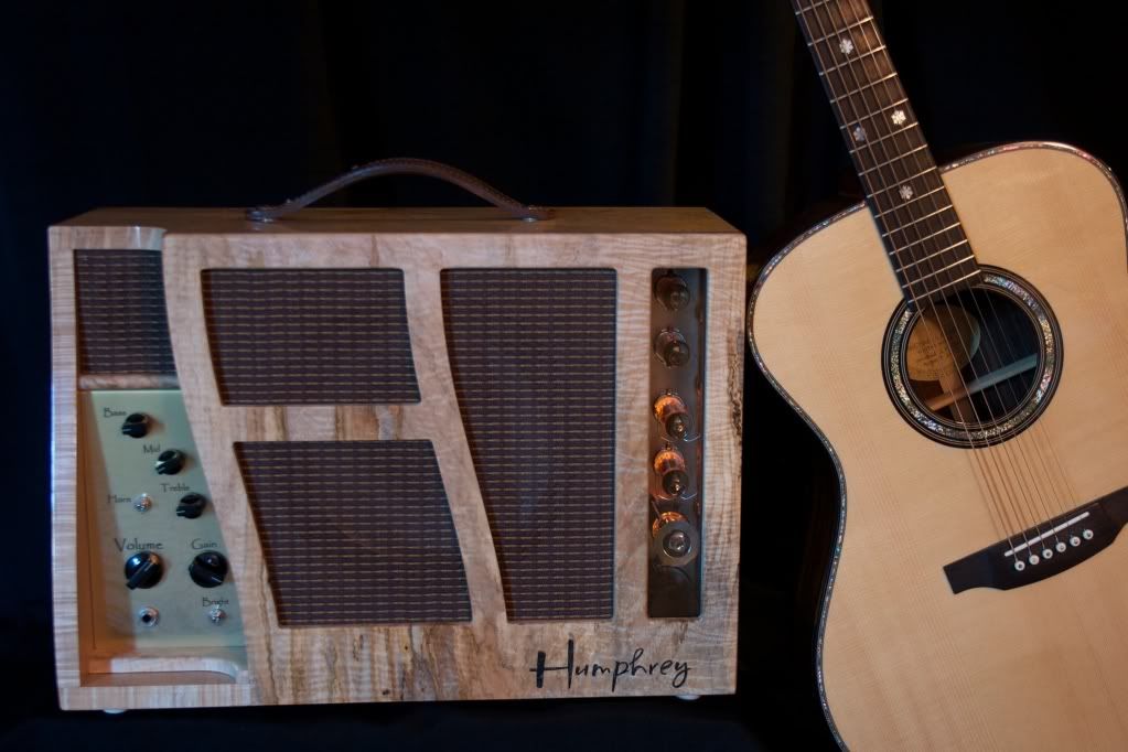
I guess my 0.02c would be: Love the mirror front amps but not the colour schemes, vintage transformers are a real worry esp. paper bobbins, and not sharing your schematics is understandable. Problem is that it's hard to defend what you are saying without them, some test data/graphs or much else.
🙂
Matthew.
I've been following this thread with real interest. Very glad to see that you have taken on the comments regarding 3 pin power connectors and earths. As a manufacturer of the equipment, safety should be your absolute priority, yes even before sound. Not worth getting sued and loosing everything if something goes wrong, because sound quality won't matter then and no liability will save you unless you have shown due diligence (Which in this case, you did not initially). Good step in the right direction though.
I see you have a real passion for what you do, which is great. But PLEASE, when you want to quote distortion figures as you have, you need to have proof of this for any kind of credibility, especially in a peer-review environment. Rightmark Audio Analyser ( RightMark Audio Analyzer. Products. Audio Rightmark ) and a cheap but decent USB sound card at the minimum would be a massive step forward. As a manufacturer, it would no doubt give you a more bonafide image too.
I guess my 0.02c would be: Love the mirror front amps but not the colour schemes, vintage transformers are a real worry esp. paper bobbins, and not sharing your schematics is understandable. Problem is that it's hard to defend what you are saying without them, some test data/graphs or much else.
🙂
Matthew.
Lars, thanks for posting that interesting use of gyrators. On an a.c. level it appears similar to what I was looking at with the CCS fed and loaded LTP with plate resistors converting the output current to a ground-referenced output. It has similar immunity to supply noises too. The gyrator circuit could also be tapped for lower output impedance at the sources if needed, keeping your original RCs for gain setting. It would be interesting to see what gyrator and coupling RC constants would work best to manage large plate swings from things like sub-sonic record rumble.
I really appreciate that the gyrators could also easily use plentiful enhancement mode Mosfets as well as the depletion type shown.
One of the wonderful things about this site it the way ideas build on each other. Yours gave me another: Perhaps a p-channel gyrator could be added for output tube grid bias to maintain stiff DC level as if one had a bias choke or driver transformer, avoiding blocking distortion and paving the way to a possible RC coupled circuit that could handle intentional grid current. Just use a bigger coupling cap and tap the source output of the driver gyrator? I haven't thought through FB stability issues though, not used to seeing what amount to LC circuits at the low-level
RC coupled gyrator-based grid bias might also be a good fit for simple low power to class A2/AB2 signal-level-based bias throttling to save energy and tube life. (That's the same lower current with lower audio concept seen in the old controlled-carrier transmitters such as the Heathkit DX-60B).
dale
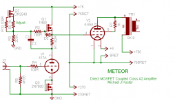
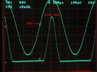
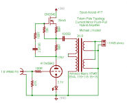
Here's a way to use a gyrator with the low impedance source output driving a power grid transmitting tube in class A2. The MOSFET provides the grid bias voltage for the output tube and drives 300V peak-peak with >50 mA peak grid current seamlessly.
Attachments
It's an anti-triode input circuit. High gm on one side, low gm on the other. Low gm side rules the sound. High gm side just inverts the current faithfully (without disturbing the tail voltage) for accurately complementary P-P. (SE like effects)
---------
Hi Michael,
I don't recall if you or Ken explored a variation earlier using OP amps for the anti-triode schemes. But I mentioned to Ken the other day another approach. For a class A P-P stage, a current sense resistor in the common B+ line (or center tap on an OT), can be used for a feedback signal to just one P-P side (grid) to get the upper "tail" current to be constant. Then the feedbacked gain element is acting like an "anti-triode". Could also use the same signal in a positive feedback mode to the "triode" side to enhance it's "triodeness". Fun and games anyway. (neg. fdbk to both sides from the top I sense would give the old WE harmonic neutralizer)
Last edited:
It's an anti-triode input circuit. High gm on one side, low gm on the other. Low gm side rules the sound. High gm side just inverts the current faithfully (without disturbing the tail voltage) for accurately complementary P-P. (SE like effects)
---------
Hi Michael,
I don't recall if you or Ken explored a variation earlier using OP amps for the anti-triode schemes. But I mentioned to Ken the other day another approach. For a class A P-P stage, a current sense resistor in the common B+ line (or center tap on an OT), can be used for a feedback signal to just one P-P side (grid) to get the upper "tail" current to be constant. Then the feedbacked gain element is acting like an "anti-triode". Could also use the same signal in a positive feedback mode to the "triode" side to enhance it's "triodeness". Fun and games anyway. (neg. fdbk to both sides from the top I sense would give the old WE harmonic neutralizer)
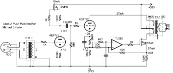
I used an op amp to sense difference in cathode current (virtual tail) plus control DC balance this self-splitting output stage. It sounds like what you're talking about. This was your idea originally as I recall (the current splitting part anyway)
Attachments
Yep, seen that one before.
This thread has now really dragged up some "unusual amps".
How about sticking in a BDT tube for P-P and some anti-triode/super triode feedbacks. Hmm, I guess that won't work, since it already has constant current. Ahh.., just feedback some of one output phase to the grid 1 of the BDT to vary the total current. That might just increase the gain on one side though (or does it become a square law/ anti square law device?). BDT is maybe too linear to start with.
Last edited:
I used an op amp to sense difference in cathode current (virtual tail) plus control DC balance this self-splitting output stage. It sounds like what you're talking about. This was your idea originally as I recall (the current splitting part anyway)
It was my Alligator. 😀
However, later I took from cathode DC bias current only driving by AC from phase splitter.
I think we (Michael, Ken, Anatolyi, myself Don and later others) were all looking at similar ideas back then.
-----------------------
Thinking about the idea of feeding back a little from one output phase of a BDT to the grid1 (current level control), has me thinking this is more than just a 2nd harmonic generator. It feeds back over and over. This probably makes for a diminishing tail of all harmonics. Might be an interesting sound.
(not that that's anything unique, seem to always end up with that) How about a low pass filter in that feedback path? Then its only got effects in the low end and low harmonics.
Last edited:
How about a low pass filter in that feedback path? Then its only got effects in the low end and low harmonics.
The presence control on a Marshall guitar amp is basically a low pass filter in the GNFB path. It reduces the amp gain, but works mostly on the lower frequencies, thereby highlighting the higher frequencies since their gain isn't being reduced as much (less feedback). It will definitely make the frequency response of the amp change unless some equal but opposite compensation was applied to the forward path.
While playing with a home made guitar amp design, the Big Dumb Blonde One got the idea to wire a tone stack into the feedback path. It made all sorts of cool sounds, which prompted the next Dumb Blonde idea. Wire a Moog resonant filter into the feedback path. Haven't tried that one yet, but I will someday.
Rolling off the gain anywhere in the loop, either in the amp, or the feedback network, lowers the amount of feedback. For the most part it's usually not a good thing. For one thing, it'll boost the higher order harmonics the most. Mismatched tubes affect the extremes more. It also doesn't give you any control over odd versus even. Depending on where the rolloff occurs, it may affect noise levels and overload characteristics differently. Early in an amp, before any stage the produces much distortion, seems to be best. I think one of the worst places is at the power amp grid. That happens when the combination of source resistance and input capacitance, perhaps boosted by miller effect in triode mode outputs. Most of the distortion is generated in the output stage. The error signal produced when the feedback signal is subtracted from the input contains plenty of inverse distortion. If it doesn't get passed all the way to the stage where it was generated (flat response and phase) the level of those distortion products can be quite high (within the amp). If the rolloff is at the output grids, the driver distortion will take those harmonics introduced by the feedback signal, and produce new products. Things like the third harmonic of one signal minus the second of another get produced. Those products aren't add or even are are as nasty as it gets. And in that example, it is a result of feedback and rolloff. Either not having feedback, or having it over as wide and flat a band as possible avoids that problem. Since it involves a very unnatural mixing of things, it's a problem when a number of instruments are present together, but with only one instrument, it can't do anything but change the amounts of normal harmonics. which may be just what's wanted then. The major issue with experimenting with FB eq or compensation networks then is stability. It's probably a good idea to have a scope connected while experimenting to make sure there isn't an ultrasonic oscillation that might cook tweeters, harm ears or cause a death glow.
I think if one is after generating harmonic effects, it might be productive to experiment with something different that won't go unstable. If one could take a graphic equalizer that had left and right ganged on each slider, it would be interesting to reverse the cut/boost connections on one channel. Then if one channel was looped through the other, the boost/cut should cancel. But put a triode stage in-between that's driven hard enough to produce some harmonics, and you could tweak what part of the spectrum was having the most harmonics made without getting much distortion from material at either end. Since some instruments (horns mostly) and voice tend to be very non-symmetrical, it would also be useful to have phase inversion switches on both the input and output of the triode harmonic generations stage. That would effect whether it tends to boost or cancel some of what's already there.
If an amp is run in inverting mode, with both feedback and signal summing to the same point, other networks to ground at that point can selectively reduce feedback in part of the spectrum, but have very little effect of frequency response.
I think a case where band-limiting the audio in the presence of distortion really makes things sound more clean, defined and open is when bi-amping or triamping. You could have an amp that adds some harmonics you like in the midrange, but it wouldn't have garble from intermod with the bass material, and wouldn't dump high-order grit into the tweeters. Plus the natural rolloff of the mid-range driver(s) filters some of the higher order harmonics from mid distortion, without removing the things that are supposed to be there that get fed to the tweeters. Of course bi-amping/tri-amping also lets one enjoy silky smooth valves for the mid and high end, while using a powerful high damped solid-state low-end when the mood fits (maybe only in hot weather?). That avoids the issue of massive output iron and core saturation too.
------------------- SPICE models can bring on a new appreciation for older power plants.
Last edited:
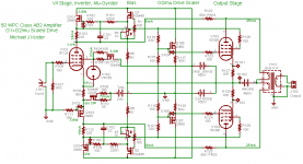
It works with class AB2 as well, driving screen grids in this experimental amp. Local feedback can still be introduced directly to the driver plates (plate and drain in this case...)
I've enjoyed seeing so many fun designs, my favorite kind of art for sure.
The gyrators/followers work so well for driving grid current. It was interesting to see the g1=g2/mu. But unlike a triode, they're both driven in phase with the plate current. Except for the ratio, it reminds me of the old cross-coupled screen taps mode that produces so much output power. I suspect that with the screen drives swapped and ratios tuned, there could be some pretty significant distortion cancellation (more like ultra-linear mode, but without the power penalty from the historic gain loss /zero-bias ceiling, since the g1's can go positive). With the ratio at mu then, I think there'd probably be too much cancellation since the grid to cathode, and screen to cathode transconductances would have drive adjusted to make currents equal and opposite. It would be much easier to optimize than transformer taps.
Thanks for the comments; though I'm not following you on the cancellation point.
The drive currents are only approximately equal and they are in phase. That makes this style drive act a lot like a zero bias (power grid) triode or g2 drive tetrode. Since it's not feedback from the plate voltage, it's hard to compare with ultralinear. Strictly speaking, it doesn't change the plate resistance.
The advantage of driving both grids over g2-only drive is the increased transconductance and therefore increased power sensitivity and drive impedance of the output stage into the OPT. This is an advantage for me because I use local feedback.
After some experimentation, I think it may be optimum overall to reduce the g2 swing and increase g1 swing to a smaller ratio than g1/g2 mu. Putting the ratio on a sliding scale allows one to control the output stage overall gm and power sensitivity (e.g. adapting to different regimes of B+, OPT ratio, local feedback, peak cathode current...)
Cheers,
Michael
- Status
- Not open for further replies.
- Home
- Amplifiers
- Tubes / Valves
- Unusual amps..