You don't want to rely on a polarized plug. There's about a million things that can go wrong (e.g., Friday afternoon wiring of your house by the electrician). There's a reason that three prong with safety ground is a standard for Class I. And why home constructors should avoid trying to make Class II work.
Hey Don,
This is just an idea that theoretically works well. But I doubt it is worth so much. We still have the grid leaks of the output tubes loading the drivers. If we take the signal from the sources of the FETs instead, the triode is practically unloaded.
The internal resistance of the triodes will provide a differential output signal based on the difference in grid voltage. For the current to stay the same, the plate voltage must change.
How about the schematic in Post #6?
http://www.diyaudio.com/forums/tubes-valves/184890-looking-new-diy-project.html
On the three prong plug issue, is there anything wrong with the polarized plug used on recent gear. It's not double insulated either?
Regards,
Randy
A 2 prong polarized plug can not be used to ground the metal chassis. Not a suitable grounding system without special isolation in the construction.
"The internal resistance of the triodes will provide a differential output signal based on the difference in grid voltage. For the current to stay the same, the plate voltage must change. "
If the gyrator on the plate is keeping the plate current constant thru the triode, then the plate can move at Mu times the grid voltage change. No need for the cathode to move at all. So how does the other triode get a signal for split phase output?
Granted, it probably works if the cathode CCS is better than the gyrators, but what assurance does one have that the split phase will be balanced? The actual gyrator impedances are more or less 2nd order effects, maybe not well matched.
Last edited:
How do you get from the stable CCS tail current to the stable grounded load resistor currents? Isn't there a follower Gm term in there? Or are we talking Mosfet Mu followers?
I am thinking Mosfets. Perhaps some would see what I was striving for better by just visualizing current sources, plate resistors to ground, and followers for the sake of driving a meaningful load. I believe that low impedance drive to an output stage is prudent even when no grid current is drawn. I'd rather avoid the influences of Miller capacitance, which output transconductance shifts (especially with SET at large signal) will modulate, introducing some incidental high frequency phase and amplitude modulation similar to what occurs with changing junction capacitance in some solid state amps. (care must also be taken to avoid that in the current sources).
But CSS and follower non-ideal possibilities aside, the main point of my alternate topology with the plate resistors to ground is to provide ground referenced outputs, potentially stable enough for d.c. coupling even without feedback, all the while being immune to power supply sag, shifts with line voltage, choke bounce, ripple, and output stage grunge (low pass filtered full-wave rectified audio).
The mechanism is simple. (consider balanced conditions for the moment, or forced balance with separate LTP cathode sources and a cap between the cathodes) The set plate CCS current minus the controlled (constant at balance) triode current is the current through the plate resistor to ground. Multiply I*R and we have the plate voltage and signal. There's no power supply term (no subtracting IR drop from supply voltage). I think the plate resistors to ground, instead of in shunt with the CSSs, approach has some serious advantanges that make it worth of consideration. That approach can be applied to other splitters and gain stages as well. It's simple but has major implications
Although this thread started on speculation about what Steve might be doing. Looking at the pictures of the one little amp and the Quad (II?), I think we got off track with the splitters. My conclusion is that they all can sound good when balanced, some being better at getting/staying there than others. But noting that the pictured amp and Quad II didn't have the same phase splitter, I did see something in common that I generally like. Perhaps others didn't notice the one pictured amp had FOUR 270 Ohm 1 W resistors with caps next to them. Although the bias could just be separate, I think another reason for that might be feedback as done in the Quad, with a tapped winding, center grounded and sides to the cathodes. Whether its a separate winding, or a grounded 4 Ohm terminal with Common and 16 to the tubes, the idea is the same.
That method of feedback has the advantage of being full-spectrum, making the amp friendlier to global FB, and the big one that usually is forgotten....
As I feel is important in the driver design, that feedback to the output cathodes helps avoid power supply grundge on the signal. Other feedback take from output plates (including that inherent in triodes) effectively improves the signal and noise immunity WITH RESPECT TO GROUND. The problem is an output transformer (except when coupled with choke(s) and cap(s) and grounded, doesn't take the output signal with a ground reference. The output is between the power supply and the plates. So every little nasty thing on the power supply becomes audible, and the internal feedback actually makes it WORSE. So the trick of feedback to the output cathodes has an major advantage that most probably weren't thinking of. And its dead simple. That's the kinding of "tuning" mod I've enjoyed making often. (along with conversion to global FB inverting mode, signal and feedback sum to same grid like an op-amp, doing away with common mode flaws, and taking the input tubes creaks, hums, hisses, microphonics, and distortion inside the feedback loop where it belongs).
Last edited:
If the gyrator on the plate is keeping the plate current constant thru the triode, then the plate can move at Mu times the grid voltage change. No need for the cathode to move at all. So how does the other triode get a signal for split phase output?
Won't the cathode have 1/2 the input voltage?
"Won't the cathode have 1/2 the input voltage?"
When the cathode current changes (normal operation) then the tail voltage swings at half the grid input swing due to the two equal transconductances (each side) handling the same current change (but opposite polarity). Ie, as the input tube varies its cathode current, the output tube let's its cathode swing 1/2 way to accept that current variation (the same swing keeps the input tube from making twice as much current variation too).
But if there is no (nada, zip....) current variation thru the input tube's cathode, the other tube does not need to let the cathode V swing to accept any current change. The tail could just as well be grounded, it's dead stationary. (ie, no current variation = no communication)
Of course a real gyrator will have some finite impedance, so there will be a tiny variation in current. That will produce a tiny shift in cathode voltage, and that will in-turn cause the output tube to vary its current by the same tiny amount. The same very high Z gyrator load will then reproduce the same magnitude of voltage swing.
So you have a race between vanishing cathode swing and increasing hyper-sensitivity to it by the second tube. All should still work (but maybe with noise issues) if the gyrators are matched ( this is excluding subsequent grid resistor loading which will probably swamp the gyrators out of the picture). But the gyrator impedances are dependant on the Rdrain of the two Fets, which may not be well matched. So balance of the two signals is dependant on a 2nd order parameter (at least for a FET drain). (someone putting some source followers on this high Z output(s) splitter will inadvertantly remove the subsequent grid loading resistors, causing likely unbalanced behavior)
Perfectly matched simulator parts will of course show no unbalance.
So although it does work, its like using a seismometer at the other end of the state to pick up your speaker signal. Or a super attenuator followed by a super gain stage.
Last edited:
OOPs, Never mind about the no 1/2 voltage tail swing issue.
I just realised that the 2nd tube can swing its cathode around without current change due to the gyrator plate loading and Mu action, so the tail is still at high Z too. So the tail should still have 1/2 the input voltage swing on it. Still requires equal qyrator (and grid R) loading to get balanced outputs though. The tail, being high Z in this case, is quite susceptible to noise pickup (much more so than the usual R loaded splitter case).
I just realised that the 2nd tube can swing its cathode around without current change due to the gyrator plate loading and Mu action, so the tail is still at high Z too. So the tail should still have 1/2 the input voltage swing on it. Still requires equal qyrator (and grid R) loading to get balanced outputs though. The tail, being high Z in this case, is quite susceptible to noise pickup (much more so than the usual R loaded splitter case).
Last edited:
Although this thread started on speculation about what Steve might be doing. Looking at the pictures of the one little amp and the Quad (II?), I think we got off track with the splitters. My conclusion is that they all can sound good when balanced, some being better at getting/staying there than others. But noting that the pictured amp and Quad II didn't have the same phase splitter, I did see something in common that I generally like. Perhaps others didn't notice the one pictured amp had FOUR 270 Ohm 1 W resistors with caps next to them. Although the bias could just be separate, I think another reason for that might be feedback as done in the Quad, with a tapped winding, center grounded and sides to the cathodes. Whether its a separate winding, or a grounded 4 Ohm terminal with Common and 16 to the tubes, the idea is the same.
That method of feedback has the advantage of being full-spectrum, making the amp friendlier to global FB, and the big one that usually is forgotten....
As I feel is important in the driver design, that feedback to the output cathodes helps avoid power supply grundge on the signal. Other feedback take from output plates (including that inherent in triodes) effectively improves the signal and noise immunity WITH RESPECT TO GROUND. The problem is an output transformer (except when coupled with choke(s) and cap(s) and grounded, doesn't take the output signal with a ground reference. The output is between the power supply and the plates. So every little nasty thing on the power supply becomes audible, and the internal feedback actually makes it WORSE. So the trick of feedback to the output cathodes has an major advantage that most probably weren't thinking of. And its dead simple. That's the kinding of mod I've enjoyed making often. (along with conversion to global FB inverting mode, signal and feedback sum to same grid like an op-amp, doing away with common mode flaws, and taking the input tubes creaks, hums, hisses, microphonics, and distortion inside the feedback loop where it belongs).
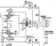
Unfortunately I didn't understand much of what you said but I have seen the " a grounded 4 Ohm terminal with Common and 16 to" part before. Lance (Jedi Master) showed a Pilot amp schematic in Audio Express. Maybe I'm wrong but it looks like the one you're talking about.
Since Steve uses vintage transformers the theory of the Quad feedback loop doesn't hold too much water but I agree with you that the "tuning process" probably doesn't happen at the phase splitter, more likely the main action takes place at the global feedback loop and at the input tube operating points.
But who knows and who cares. My amp sounds fantastic as it is.
Sorry, schematic is blurry. Not my fault.
Attachments
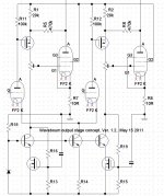
Anyway, if one wants to minimize anode load in a LTP this elaborate topology could be the way to go (post 611).
Lars, thanks for posting that interesting use of gyrators. On an a.c. level it appears similar to what I was looking at with the CCS fed and loaded LTP with plate resistors converting the output current to a ground-referenced output. It has similar immunity to supply noises too. The gyrator circuit could also be tapped for lower output impedance at the sources if needed, keeping your original RCs for gain setting. It would be interesting to see what gyrator and coupling RC constants would work best to manage large plate swings from things like sub-sonic record rumble.
I really appreciate that the gyrators could also easily use plentiful enhancement mode Mosfets as well as the depletion type shown.
One of the wonderful things about this site it the way ideas build on each other. Yours gave me another: Perhaps a p-channel gyrator could be added for output tube grid bias to maintain stiff DC level as if one had a bias choke or driver transformer, avoiding blocking distortion and paving the way to a possible RC coupled circuit that could handle intentional grid current. Just use a bigger coupling cap and tap the source output of the driver gyrator? I haven't thought through FB stability issues though, not used to seeing what amount to LC circuits at the low-level
RC coupled gyrator-based grid bias might also be a good fit for simple low power to class A2/AB2 signal-level-based bias throttling to save energy and tube life. (That's the same lower current with lower audio concept seen in the old controlled-carrier transmitters such as the Heathkit DX-60B).
dale
On the three prong plug issue, is there anything wrong with the polarized plug used on recent gear. It's not double insulated either.
Nothing wrong with it at all in theory. IN THEORY. Can you guarantee that the wall sockets weren't wired backwards, perhaps by some electrician's helper who forgot the color code?
Can you guarantee that the power company will ensure load balance at all times? I've seen "ground" neutrals go as much as 60Vrms above ground. (One guy wanted to beat the crap out of me for pulling the wrong breaker when he touched a "ground" wire and a cold water pipe at the same time. I pulled the right breaker, but that third wire "ground" was considerably elevated by load imbalance.) These days, you have four wire systems: +120Vrms, -120Vrms, "ground", and the real ground connection.
Can you guarantee your end user won't ever use an extension?
Can you guarantee that your end user with a polarized plug and old fashioned, unpolarized, wall sockets won't "solve" the problem with a file or just plain brute force?
No? Beginning to see the problem here? You can't count on it.
Wavebourn posted a scheme some while back that used a P channel Mosfet, controlled CCS plate load for a driver stage, for use with Schade feedback (resistive attenuator) from the output tube's plate back to the P channel source resistor. Since the P channel is B+ referenced, and the Schade feedback is B+ referenced thru the OT, PSRR is enhanced. Only current is reflected back to the driver plate. Plus the driver is high Z loaded instead of the usual low Z Schade network.
-----------------------------------------
Bob Carver uses a 6AL5 diode with it's cathode connected to an output tube grid and it's plate connected to a negative bias. When the input signal gets large enough to make the 6AL5 conduct, it can null out the tube's own grid conduction to avoid bias shift after the coupling cap. (an ordinary diode would work too, just a DC restorer circuit)
By using less negative bias on the 6AL5 plate, it can be made to shift the output tube's grid bias (coupling cap) positive instead of just holding it steady. This would work for a signal based bias adjuster. Carver mentions using it this way. It would tend to flat top the drive signal though when the amplitude suddenly increases above the bias threshold.
Last edited:
The BDT (beam deflection tube) phase splitter automatically gives AC balanced outputs, just like a differential/CCS tail stage.
Although it's been mentioned for the paraphase to connect the cathodes together ( and with not much effect for the floating paraphase case), I don't think I've seen any info on putting a CCS tail on it too.
In any case, the BDT can be configured as a paraphase by putting a divider network to the 2nd deflector, and it automatically has a CCS tail equivalent giving it matched AC output amplitudes. Not sure what happens for the floating paraphase network case here since it's already AC balanced, probably just determines the AC balance on the two deflector signals. (which doesn't affect the output AC balance, but maybe influences the distortion profile)
The BDT looks like the real sleeper PI.
Last edited:
Wavebourn posted a scheme some while back that used a P channel Mosfet, controlled CCS plate load for a driver stage, for use with Schade feedback (resistive attenuator) from the output tube's plate back to the P channel source resistor. Since the P channel is B+ referenced, and the Schade feedback is B+ referenced thru the OT, PSRR is enhanced. Only current is reflected back to the driver plate. Plus the driver is high Z loaded instead of the usual low Z Schade network.
-----------------------------------------
Yes, but I did not use there CRT as a phase splitter. 🙂
Attachments
Yes, that's it. Although I was thinking it had the triodes pulling down on the P-channel drains instead of the gates, so that it would be high Z current loaded for super PSRR.
"Yes, but I did not use there CRT as a phase splitter. 🙂 "
Well, BDT's can do 20 mA, not like it's only microAmps deflected. I'm biased though, since I got a big box of them cheap in that big Vacuum Tubes Radio Tubes - 5,000 different tubes in stock - Over 10 million tubes! overstock tube sale a year or two ago.
I see 6ME8 are still $1.00
But 6JH8 are $5.00
Last edited:
don't think I've seen any info on putting a CCS tail on it too.
Someone might have tried and dumped it.
Will reduce even harmonics even more compared to a LTP at the same time as it enhances uneven. What a nightmare....
I see 6ME8 are still $1.00
But 6JH8 are $5.00
6AH6 is $3, 6AU6 is $5. I bought bunch of mil spec 6J4P and 6J5P on epay for less than $1 a peace.
Yes, that's it. Although I was thinking it had the triodes pulling down on the P-channel drains instead of the gates, so that it would be high Z current loaded for super PSRR.
I see 6ME8 are still $1.00
But 6JH8 are $5.00
It looks like the source has a batch of 315 3CB6s for $100. Wired in 6 V pairs those would be great for a group project, and it'd be easy enough to still support normal 6 V types. I like the higher GM 6EW6 better, but those are $5 each.
It looks like a depletion mode P-channel would be the simplest for the supply rail referenced feedback with nothing else to power it but the destination for the output current. I'm not sure if such parts are readily available. It's lookinging like just about anything else would require some extra clean current from somewhere. A current mirror would have similar issues to a p-channel enhancement part, needing an input clean-current sink along with the plate voltage feedback resistor to prevent cut off on the upswing.
It's funny that you mentioned d.c. restoration. Long ago I used to mod my tv sets, and later tried the audio trick as well. Going d.c. coupled with zener level shifting looked even better, but going whiter than white on no signal required protection. What I had in mind for the bias control of an amp was more complex, duplicating something I'd made for a compressor limiter. It'd adjust the bias based on peak audio level, but ramping it back down had a delay that wouldn't start if audio was still peaking within 6 dB of the previous peak. It also was designed not to act on the first 10 ms IIRC, to avoid going crazy with record pops. So an amp would occasionally allow a few class AB transients.
On the business of some wanting some added second harmonic from amps, I wonder if anyone has ever provided switching to reverse BOTH input and output phase. That would not reverse the phase of what the listener hears, but it would change the direction of the higher peaks of the audio to match the direction that the amp kicks higher. Horns and voice typically have waveforms that have narrow high-peaks one direction (I think it's positive if the absolute phase is correct), and a wider flatter pattern on the negative side. As long as the areas under the curve are the same, there can be higher peaks one way without a d.c. component. Anyway, the phase agreeing thing should make a large difference in the sound when a low FB SET amp is driven to where there is some significant 2nd being added. With the phase of source material having a 50/50 chance of being right, the amps are likely to unexpectedly agree with some recordings more so than others (even same type of music). Now those reading this know a reason why. The absolute phase matters too. The explosion of a cannon or initial whack of a snare drum should push us back, not hit us with vacuum. I should take a microphone and confirm that it's the up pressure release (+) side of voice peaks that is spikier. On a SET amp, it's the positive current (negative voltage) side that is spikier which means they actually should be flipped compared to what gives correct absolute phase.
I think an add-on to show which way material peaks higher might be desirable for SET amps. Meanwhile, fire up those scopes?
"It looks like the source has a batch of 315 3CB6s for $100."
I also see several boxloads of 6CB6 listed for about the same price.
But then 6JC6, 6JD6 and 6HM6/6HT6 lists individually there at $1, so why bother.
I also see several boxloads of 6CB6 listed for about the same price.
But then 6JC6, 6JD6 and 6HM6/6HT6 lists individually there at $1, so why bother.
- Status
- Not open for further replies.
- Home
- Amplifiers
- Tubes / Valves
- Unusual amps..