OMG, I just found the ideal feedback resistor value (22k). Push pull amps with a floating paraphase and good tubes (2 RCAs 5692+ 6v6's here) sound awesome, just awesome. I don't want anything else. Over and out.
You sound like you have just invented fire..LOL 😀
Nice to see the 6V6 in circuit 🙂
Regards
M. Gregg
LOL. My over enthusiasm got the better of me. Maybe it was the wine after all. 😱
I think your enthusiasm is great 🙂
What did you find with the "overcomp" pot in the F Paraphase..You said it did not work as expected?
Regards
M. Gregg
I am a little confused with the earlier discussion about pot values, hope this is not out of context.
It's my understanding and experience that higher value pots retain high end fidelity, whereas lower value pots will bleed off treble in any position.
Anything under 1M will bleed off a noticeable amount of treble.
A good example is in electric guitars.
Single coil pickups are brighter sounding then a hum bucker. Single coils use around 250K pot to bleed off some treble.
Hum bucker pickups are a little darker sounding so a 500K is used to retain more treble.
Jimi Hendrix used single coils and 1M pots for a very lively and bright sound, with maximum tone potential.
I think thats where "davesnothere" is coming from and he is correct.
Loading something like a preamp resistively normally does not bleed off treble, generally the opposite is true and the response is extended when loaded. If the resistance to ground is cut in half, a given amount of capacitance across that will start to roll-off the treble at twice the frequency it would have. Lowered impedance driving the miller capacitance of the input stage also sees reduced roll-off from that. Even away from hum sources, for the same reasons we'd never see long cables on a high impedance microphone or phono cartridge.
What you're seeing with guitar pickups is a special case. It's a highly inductive source which combining with cable capacitance is forming an LC filter that has a peak (boost) in the high end response just before it rolls off. Increasing the resistive loading on that lowers the Q bringing down the peak. There's a point where response is flatest, then still more loading causes rolloff, but it's the inductive reactance that deserves the blame (much like leakage inductance in an output transformer) not the resistance. In your case I can see how the brighter sound from lighter loading would be useful.
I usually use pots of no more than 10K, which is a light load for op-amps, but I do add a follower output stage to any tube gear that doesn't already have an output buffer. Either a tube or FET works well. Just an ordinary RCA style interconnect cable is typically several hundred picofarads, which causes noticible loss at the high end with high impedance, even 50K, outputs. Many older tube designs were somewhat cut-corner. Some marginally designed units have tone control circuits unbuffered at the output, leading to response that changes with cable length and load resistance changes. Avoiding really high impedances gives flatter response and less pickup of hum and noise.
I nearly always design or mod amps to run in inverting mode, no feedback to input cathodes... going right to the grid (using a larger feedback resistor to allow a bigger one on the low side too, keeping the product of the R and C the same if there's a lead-compensation capacitor across the feedback resistor. Phase has to be flipped later in the amp to make it negative feedback). The input signal comes in to the grid through a resistor that's basically the lower half of the feedback divider (goes to signal instead of ground, just like with an inverting op-amp). I use a shorting jack or add a resistor across the input to limit the amount of feedback when nothing is plugged in. That approach reduces any distortion (and hum/microphonics!!!) from the input tube while the normal cathode-connected feedback mode does NOTHING to help that stage. It also prevents input circuits from needing to handle any common-mode signal at all. Many circuits degrade, especially things like current sources at high frequencies, when seeing large common mode signals. The inverting mode trick is what allowed NE-5534's to sound great 30 years ago in spite of their known H.F. common-mode distortion problems.
Oh, if there is a small coupling cap ahead of a reduced resistance, the increased load WILL roll off low-end. A larger cap solves that problem. Sources that distort when driving any current still do need a buffer added .
Last edited:
You said it did not work as expected?
Yeah. Maybe it was a dumb idea using it inside a global feedback loop.
Lars, that design still doesn't overcome the fundamental issues of the paraphase- one side has a different number of rolloffs and distortion pattern than the other, the balance is dependent on tube and tube age, source impedances are different from side to side. What do you see as the advantage over a much simpler (and inherently balanced) diff amp with a CCS tail?
A CCS tail, with mu followers on the output, shunted with matched load resistors to clearly define gain and broaden bandwidth, would seem to give better performance yet. The total current could be cranked up for higher transconductance but the current swing percentage through the resistors would be less of the total lowering distortion. It'd be inherently balanced and low output impedance. If used with a stable precise supply voltage and well controlled adjustable current (to set output bias) on the bottom, I'd think outputs might be stable enough to be taken through bypassed (level-shift) Zeners pulled down by current sources to directly drive output stages needing grid current. The mu followers or something would need to be inhibited during warmup to avoid excess positive drive voltage before the LTP comes up. Maybe a low-on resistance switch in the output cathode(s) would be easier if linear enough, just RC constant to delay on-state bias, or maybe use rising cathode voltage from an input stage designed with enough drop there... (it's okay to get unusual on the unusual amps thread, yes??)
Afterthought to self: Putting the plate load resistors to ground instead of the positive supply removes dependence on a quiet supply and stable supply voltage, only the current source behavior of the mu followers must be accurate.
Last edited:
I don't think that you don't need the mu follower complication most of the time- if the plate resistors are matched and loads are equal (which is the case for any class A1 or AB1 amp), you've got balance. The mu follower (and CCS-loaded voltage amp) will give lower even order distortion, but that's the part that cancels in the pp output stage anyway. The mu follower will have lower source impedance, so that's a plus that the extra complication (extra tubes, extra heater supplies) gets you. For a given B+, a mu stage will likely have reduced swing ability, so that's another minus.
Power supply noise is common-mode, so is even less of a problem in that position as usual.
Power supply noise is common-mode, so is even less of a problem in that position as usual.
I don't think that you don't need the mu follower complication most of the time- if the plate resistors are matched and loads are equal (which is the case for any class A1 or AB1 amp), you've got balance. The mu follower (and CCS-loaded voltage amp) will give lower even order distortion, but that's the part that cancels in the pp output stage anyway. The mu follower will have lower source impedance, so that's a plus that the extra complication (extra tubes, extra heater supplies) gets you. For a given B+, a mu stage will likely have reduced swing ability, so that's another minus.
Power supply noise is common-mode, so is even less of a problem in that position as usual.
Well as with push pull output stages, balanced conditions cancel hum at idle. The cancellation is something of an illusion however since the stage isn't balanced (instantaneously) when we have the swing of a signal. The hum conditionally introduced in that way appears as intermodulation. Try a noisy supply and look at the 120 Hz sidebands on a test tone. Think of the stage as acting like a balanced modulator. In fact, with tubes, a LTP is the usual way to make a balanced modulator (the signal being balanced out usually introduced in the cathode leg).
The idea about mu followers with plate loads to ground (but output from the source of the follower) is a bit of a radical one, because it makes the output voltage ground referenced driven by current instead of supply referenced. So beyond the supply noise immunity considerations, direct coupling would only need stable currents to produce stable drive. We can easily get the stable currents and have D.C. drive that doesn't need readjustment when the driver tube is changed, and its a gain stage! The supply voltage could vary without upsetting the voltage to the next grid. That stability, combined with the low output impedance of the followers has the potential to make the stage a good d.c. coupled driver. Even if no grid current is needed, d.c. drive will eliminate blocking distortion, a pole in the low-frequency path, and a possible source of capacitor distortions. There's no real need for a regulated bias supply either, just a stable adjustable current source in the LTP to set bias, and clean current sources for the output grid pull-downs. (actually even those aren't needed if the mu followers and zeners are stiff enough) A trim pot between cathodes, slider to CCS, can provide dc balance trim if needed without disturbing total currents or adding noise from any supply.
Last edited:
How do you get from the stable CCS tail current to the stable grounded load resistor currents? Isn't there a follower Gm term in there? Or are we talking Mosfet Mu followers?
Last edited:
Well reading and chewing over this again,
Not for any other reason than to see how the F Paraphase holds up..🙂
The bit subtitled The amplifiers
Link:
Master Builders: Lance Cochrane And Jim Nicholls Review By Dick Olsher
Definatly worth a re-read..
Reading this....
The reviewers seem convinced..🙂
Regards
M. Gregg
Not for any other reason than to see how the F Paraphase holds up..🙂
The bit subtitled The amplifiers
Link:
Master Builders: Lance Cochrane And Jim Nicholls Review By Dick Olsher
Definatly worth a re-read..
Reading this....
The reviewers seem convinced..🙂
Regards
M. Gregg
Last edited:
the balance is dependent on tube and tube age,
Hey SY,
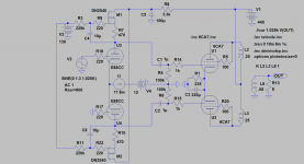
Came to think of it about drift in the FP. How much imbalance from tubeaging will you get from a anodefollower that has a local feedback of let´s say ca 30dB? Shouldn´t be much.
Anyway, if one wants to minimize anode load in a LTP this elaborate topology could be the way to go.
Attachments
Last edited:
Lars, looks nice, but have you tested that design to see if it will actually split the signal?
If both tubes are constrained to run at constant current, it's not obvious that any cross feed occurs on the tail. But then the other side should also be hyper sensitive to any cathode swing too.
If both tubes are constrained to run at constant current, it's not obvious that any cross feed occurs on the tail. But then the other side should also be hyper sensitive to any cathode swing too.
How much imbalance from tubeaging will you get from a anode follower that has a local feedback of let´s say ca 30dB? Shouldn´t be much.
Sorry, didn't see this before. No, probably not much- 30dB covers a multitude of sins. But if you use a tapped resistor version, then lots of variation with aging since the balance will depend on mu and rp. And of course you still have the inherent imbalance of rolloffs and distortion spectra from side to side that you don't have with an LTP or cathodyne.
Lars, looks nice, but have you tested that design to see if it will actually split the signal?
If both tubes are constrained to run at constant current, it's not obvious that any cross feed occurs on the tail. But then the other side should also be hyper sensitive to any cathode swing too.
The load is a gyrator, hence not constant current. I use something similar in my phono stage, actually works quite well with depletion mode mosfets and reasonably well with high transconductance triodes as well.
Just noticed this old thread came back from the dustbin:
http://www.diyaudio.com/forums/tubes-valves/37499-john-swensons-my-eyes-revolutionary-preamp.html
Which reminded me that the Beam Deflection Tube (BDT) is another way of making a phase splitter. Probably the most exotic of all. And it can even be configured as a paraphase/floating para too I think.
------------------
"The load is a gyrator, hence not constant current."
The gyrator is not constant at DC since it balances to a level by adjusting current, but for audio freqs. it's a constant current source. (C4 and C8 maintain a constant voltage across the Fet gate and source resistor in the audio freq. range.)
Last edited:
I think the key is to have a better cathode CCS than plate (the gyrator is still pretty CCS-like at AC).
IMLE the gyrator seems to work OK as a plate load even in balanced stages as long as there is some sort of reasonable CCS or very long tail resistance in the cathode circuit. (I've also had it not work too well..) The design discussed has the requisite CCS in the cathode circuit.
Something else to note with the gyrator is that in fixed bias implementations like this one the maximum load impedance that can be achieved is roughly equivalent to the resistance of the bias network in the gyrator circuit which in this case is 220K.
My tube implementation is limited to about 60K which with 15mA flowing through it is not so bad when you consider that a 60K resistor at this current would drop 900V across it, and the gyrator drops about 140V.. The rps of the tubes loaded this way is 1.2K - 2K..
have you tested that design to see if it will actually split the signal?
Hey Don,
This is just an idea that theoretically works well. But I doubt it is worth so much. We still have the grid leaks of the output tubes loading the drivers. If we take the signal from the sources of the FETs instead, the triode is practically unloaded.


How about the schematic in Post #6?
http://www.diyaudio.com/forums/tubes-valves/184890-looking-new-diy-project.html
On the three prong plug issue, is there anything wrong with the polarized plug used on recent gear. It's not double insulated either?
Regards,
Randy
http://www.diyaudio.com/forums/tubes-valves/184890-looking-new-diy-project.html
On the three prong plug issue, is there anything wrong with the polarized plug used on recent gear. It's not double insulated either?
Regards,
Randy
- Status
- Not open for further replies.
- Home
- Amplifiers
- Tubes / Valves
- Unusual amps..