a 100k pot is bad audio alchemy. Let me put it this way, its dumb to attenuate the amp that is what the preamp is for. And I don't know why 100k seems to be the first choice for diyers there only 4 instances where 100k really works like it should. this isnt one of them.
Say what??????
remove 100k pot, install 500K pot
And a 500K pot is better how? Removing the 470K resistor even makes things worse. With a 500K pot and no resistor, at mid volume the best case drive impedance that the input tube sees is 250K (assuming a zero impedance source). With a high gain triode tube (12AX7 is mentioned) the Miller capacitance and the pot resistance will form a low pass filter and roll off the high frequencies. If the pot is too large the amps frequency response will change as you adjust the volume.
In my amps that use a 12AT7 a 100K pot is the highest recommended value anything higher will cause an audible and measurable high frequency loss. The amps using a 5842 must use no larger than a 50K pot.
With most modern sources capable of driving low impedance loads, why would you use such a large value pot.
There is another l´Audiophile design with 6V6 and floating paraphase and has a part that shows all paraphase variations. Have almost all the old magazines. Will try find it. This one with plate to plate feedback together with triodes and old style paraphase does not look so nice.
I wasn't talking about the pot at the input anyway.......because I have no pot at the input. The schematic I posted has nothing to do with the amp I'm testing. On the other hand the schematic you posted has a floating paraphase and that's where my pot is. Fine-tuning the ratio of the divider.
Sorry but that does not make sense to me, maybe you want to explain it.
And I don't know why 100k seems to be the first choice for diyers there only 4 instances where 100k really works like it should.
Sorry but that does not make sense to me, maybe you want to explain it.
Un amplificateur tubes stable et performant , PP 6V6 (F.Blesbois)
Wouldn´t build it with SRPP and that drivertube though. But it is a good article.
Wouldn´t build it with SRPP and that drivertube though. But it is a good article.
Lars, that design still doesn't overcome the fundamental issues of the paraphase- one side has a different number of rolloffs and distortion pattern than the other, the balance is dependent on tube and tube age, source impedances are different from side to side. What do you see as the advantage over a much simpler (and inherently balanced) diff amp with a CCS tail?
Hi SY,
First of all, my discussion wasn´t about FP against LTP. It was about how to design a FB in a best way.
I know all the theroretical shortcomings, but when compared to concertina that I(and probably also you) like, they actually share close to the same harmonic pattern in a perfect world. The concertina also get different source impedance, but only when driving the output device hard(grid current). The LTP gets cancellation of the even harmonics which makes it different to the two other.
The difference in harmonic pattern and rolloff by the the two driver halfs isn´t the most important, what you get at the amp output is. As I mentioned earlier you can actually unbalance the FP, by reducing gain in the anodefollower, to get the same harmonic pattern as the LTP. Don´t ask me why, but maybe you or someone else will explain?
Tube aging doesn´t mean that much as you easily can check and you anyway need to check your output tubes more often. Also the driver can actually drift quite a bit before anything dramatic happens.
The bottomline is I have always prefered FP soundwise. But I also prefer the "small accordion" to the LTP 😉 .
Last edited:
Well, a concertina will show equal and low source impedance unless you run into grid current, but no-one would have a concertina or any other phase splitter drive an AB2 stage directly. So in an apples-to-apples comparison, the concertina will show better bandwidth, far better balance, insensitivity to tube variations or aging, and far lower distortion.
The devil on my other shoulder points out the gain difference- the concertina achieves its performance by using 100% feedback, so the gain is roughly unity, whereas an FP or LTP will have a gain of something like 0.4 mu. So to make the comparison fairer, one can consider a grounded cathode voltage amp direct coupled to a concertina. Now the gain is higher (as high as mu, if you use a CCS plate load), but the balance is still essentially perfect. And I will wager that the distortion pattern looks a whole lot better as well (especially considering the distortion of the whole amplifier, where the even order from the phase splitter sides, being equal and opposite, will cancel in the output stage), even before considering the extra 6dB available for the feedback loop.
The disadvantage is swing- a concertina will have a harder time when a high voltage swing is needed, and that's where a differential circuit like an FP or LTP can have an advantage. But even then, an LTP will have equal source impedance, equal rolloffs, and essentially perfect balance even with tube variation and aging- the FP won't. The two circuits will have similar gain. So I'm still struggling to see why you would prefer an FP.
I am a little confused with the earlier discussion about pot values, hope this is not out of context.
It's my understanding and experience that higher value pots retain high end fidelity, whereas lower value pots will bleed off treble in any position.
Anything under 1M will bleed off a noticeable amount of treble.
A good example is in electric guitars.
Single coil pickups are brighter sounding then a hum bucker. Single coils use around 250K pot to bleed off some treble.
Hum bucker pickups are a little darker sounding so a 500K is used to retain more treble.
Jimi Hendrix used single coils and 1M pots for a very lively and bright sound, with maximum tone potential.
I think thats where "davesnothere" is coming from and he is correct.
Please tell me why true real resistive component with no imaginary part should influence the frequency response when no other component is involved.
I state that is the other way round. A high-resistance circuit design has disadvantages. Stray fields will induce hum and parasitic capacities will worsen the frequency response.
Even the worst preamp should be able to drive a 10k input pot. today.
I state that is the other way round. A high-resistance circuit design has disadvantages. Stray fields will induce hum and parasitic capacities will worsen the frequency response.
Even the worst preamp should be able to drive a 10k input pot. today.
Because it bleeds high frequencies straight to ground.
A 1M volume pot will let high frequencies shunt straight to ground, even when on full.
A 500K volume pot will let even lower "treble" to be bleed to ground.
A 250K volume pot...even lower.
A 1M volume pot will let high frequencies shunt straight to ground, even when on full.
A 500K volume pot will let even lower "treble" to be bleed to ground.
A 250K volume pot...even lower.
Hey SY,
Noone would compare a concertina to the two others without its gainstage(preferably DC-connected). The low distortion of the concertina(and the anodefollower in the FP) itself is unintereseting in this context.
The FP do not have again of 0,4mu, so the LTP and FB does not have the same gain. Nothing strange with that as the input triode of the FP determines gain. When comparing the FP and the Concertina they will have close to the same gain and harmonicstructure whereas the LTP will be ca -6dB down in gain and have well cancelled even harmonics compared to the two previous PIs. It seems to be distortion cancellation(before the output stage) in the LTP PI only. Must dig deeper into this......
Could the cancelled even harmonics in the LTP have something to do with my preference of the LTP and Concertina? I don´t know and I don´t mind.
My mistake, you're correct, the FP gain is close to the voltage amp/concertina and higher than an LTP. The LTP will indeed cancel even harmonics, which helps linearity.
I also like the concertina and the LTP not so much but I have no idea why. Maybe because they sound different?
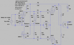
Thanks for the schematic.
This is the topology I would start out with if building a Floating Paraphase
Thanks for the schematic.
Because it bleeds high frequencies straight to ground.
A 1M volume pot will let high frequencies shunt straight to ground, even when on full.
A 500K volume pot will let even lower "treble" to be bleed to ground.
A 250K volume pot...even lower.
But how can a simple pot distinguish between high and low frequencies ? 😕
But how can a simple pot distinguish between high and low frequencies ? 😕
Its the amount of resistance in series with the grid..
When you have the wiper at mid position the top half of the pot is in series with the grid..when you move the wiper the resistance in series with the grid alters.
Just for fun link:
http://www.aikenamps.com/MillerCapacitance.html
Regards
M. Gregg
Last edited:
On the previous link (Mr Miller),
Its interesting to look at the 3rd paragraph from the bottom and Steves comment about only using low gain stages and adding another if its not enough..🙂
Regards
M. Gregg
Its interesting to look at the 3rd paragraph from the bottom and Steves comment about only using low gain stages and adding another if its not enough..🙂
Regards
M. Gregg
OMG, I just found the ideal feedback resistor value (22k). Push pull amps with a floating paraphase and good tubes (2 RCAs 5692+ 6v6's here) sound awesome, just awesome. I don't want anything else. Over and out.
I know the miller effect very well, but that still doesn't give a reason for using high value pots.
The other way round it makes more sense. 500k in series with the grid gives a frequency dependant potential divider. with just 5k the effect is much less.
But please consider the low value of the Ca-g in a tube. For a preamp tube like 12AT7 it's just 1.45pF. This becomes a problem with power triodes.
But how can a simple pot distinguish between high and low frequencies ?.......Please tell me why true real resistive component with no imaginary part should influence the frequency response when no other component is involved.
It can't and doesn't. However a simple pot isn't used by itself. In the circuit discussed originally the pot is connected to the grid of a tube. The tube has several capacitances associated with it. There is the grid to cathode capacitance, and the "Miller capacitance" which is the product of the grid to plate capacitance and the tubes gain in a triode. Together these capacitances can be 10 to 100 pF. The effective equivalent resistance of a 500K pot set at half volume (assuming a very low source impedance) is 250K. Now put a 250K resistor in series with your signal followed by a 100pF capacitor to ground and you have a textbook low pass filter.
A good example is in electric guitars. Single coil pickups are brighter sounding then a hum bucker. Single coils use around 250K pot to bleed off some treble.
Again the pot isn't used by itself. Guitar pickups are coils of wire, in other words inductors. They appear like an inductor in series with a signal source. Tthere is some capacitance and resistance but the inductance dominates. They are also rather high impedance sources. The wiring and the external cable capacitance can create resonances that fall in the audio band. In general a lower value pot creates a low pass rolloff effect, but a blanket statement can not always be made with regards to pots, and pickups. It depends greatly on the pickup itself, how the guitar is wired and the length and quality of the cable used to connect the guitar to the amp. In general a higher value pot will allow the guitar to sound brighter, but it will make the cable more dominant in controlling the tone. Put a 1 meg pot in a guitar, set it to half throttle, and play into a 20 foot cable. You will have no treble at all.
In any circuit there are NO pure components, and none are used alone. All the capacitances and inductances created by imperfect components, component interaction, and even wiring need to be considered to fully understand how things interact. These interactions become a much bigger factor as the impedances in a circuit are increased. This is often the reasons that some designs need to be "tuned".
- Status
- Not open for further replies.
- Home
- Amplifiers
- Tubes / Valves
- Unusual amps..