Scott, thanks for posting the schematic! It's a nice little amp, and how very nifty to come up with an entire three-stage guitar amp heated by a single filament in one bottle! -Flieslikeabeagle
Glad to post the schematic for the version I built. I wish I could claim full credit! However I got the idea from the Squirrel Monkey, although I did modify it to include a conventional all-tube power supply among a couple of other changes. I'll tell you one thing though, if you even look at this tube cross-eyed, it will oscillate!
I am very happy with the sound though. It's able to do clean or crunchy in a good way.
I'll tell you one thing though, if you even look at this tube cross-eyed, it will oscillate!
I know. I built a full on TV jammer using two of them. I got the idea of using 2 tubes for a push pull amp. I tried an LTP (Marshall style) phase inverter using the two lower Mu triodes, and the higher Mu triodes for gain stages. This makes for a furball of a PC board which can't be tamed. I tossed it aside and haven't been interested in revisiting it.
There are two other tubes that will plug into the same socket and one of them was less of an oscillator than the 6AF11, but I don't have the numbers right now.
Sometimes 'tis better to remain silent and appear lazy than to open one's mouth and remove all doubt.
Actually if YOU choose not to read these 136 pages, YOU have suffered a loss. In reading this thread the real winners will present themselves. My congratulations to all of them!

I mean...I'll read through it eventually...but I just wanted to know who the winners are.
I know. I built a full on TV jammer using two of them.
Ha! That tube is finicky. However the amp I built, unbelievably, does not oscillate. I have Triode 2 biased WAY down in the curves. If you notice it is drawing a whopping 0.3 mA! Sounds really good. Very low wattage, but for a practice amp it sounds very close to a 5F1 circuit.
It may very well be possible to do a push-pull with the 6AF11, but it would definitely be a labor of love.
Somewhere in those 136 pages you will find a post by the contest organizer explaining how he was taking time off to tend to his fathers serious illness. He has only been seen intermittently since then. As someone who has gone through this twice last year, I can relate and do not expect a formal judging of winners and losers any time soon if at all.
So sorry to hear this! My thoughts are with the organizer. Sorry to hear you've been going through that as well. 🙁
Technically only Tubekit's amplifier and one of mine delivered a posted bill of material and a schematic by the designated date. My second amp is still being finished slowly in my spare time. The cabinetry is nearly complete and I will plug the amp in for the first time in about 4 months soon. The results will be posted here. There are several posted schematics and it looks like some of them have been built by other interested builders.
Sounds great! I look forward to the results.
As rcavictim stated this thread was, and still is a place for someone to read and learn a lot about designing and building a vacuum tube guitar amplifier. It is also a good thread to mine for ideas, schematics and pictures.
Yes there are some strong opinions and even a temper tantrum or two. it seems that we all can't agree on he definition of a vacuum tube amplifier, or exactly how to add up the cost of building one, but most of the opinions are valid.
Haha, of course we can't agree on the definition of a tube amp 😀
If you are even dreaming of building a guitar amp on a budget, read the whole thread. If you just want to clone a Marshall or Fender, it is still worth reading to learn the pitfalls that we all found in doing this.
For sure, I plan on reading the whole thing.
Originally Posted by tubelab.com
If you are even dreaming of building a guitar amp on a budget, read the whole thread.
I'll second that observation!
Scott
If you are even dreaming of building a guitar amp on a budget, read the whole thread.
I'll second that observation!
Scott
but I just wanted to know who the winners are.
The member who started this thread and proposed the challenge stated in post #1149 that:
I am currently dealing with my father's terminal illness. My absence has nothing to do with 'disgust'; it has everything to do with real-life demands on my time and energy.
He has not been back here since, thus no official winner was determined. There were several designs posted that were worthy of duplication, perhaps the true winner is the designer of the amp that you want to copy.
So sorry to hear this! My thoughts are with the organizer. Sorry to hear you've been going through that as well.
I lost my mother and my mother in law this year. My mother in law lost her 4 year battle with cancer last July sarting a probate mess that is still going on. Yes this has sucked up much of my time and kept my wife away for months at a time. I don't know the thread starters situation, but it can take a while to recover from it all.
The thread alone is a learning experience for all involved, and I don't think any of the participants really care who the winner is.....We all are.
The member who started this thread and proposed the challenge stated in post #1149 that:
He has not been back here since, thus no official winner was determined. There were several designs posted that were worthy of duplication, perhaps the true winner is the designer of the amp that you want to copy.
I lost my mother and my mother in law this year. My mother in law lost her 4 year battle with cancer last July sarting a probate mess that is still going on. Yes this has sucked up much of my time and kept my wife away for months at a time. I don't know the thread starters situation, but it can take a while to recover from it all.
The thread alone is a learning experience for all involved, and I don't think any of the participants really care who the winner is.....We all are.
I lost my father to leukemia when I was in high school. Seriously, **** cancer. I'm sorry. 🙁
**** cancer. I'm sorry.
When my boss was dying of cancer nearly 10 years ago he made the statement that "cancer steals dreams". He was right. Not just dreams of the person with cancer, it affects the people around them too.
His son dropped out of college to care for him, and never returned since the college money was spent on care.
We were told that my mother in law had "months to live". My wife gave up her job and moved in with her mother (1200 miles away) to care for her in her final days. She enrolled in some experimental program and lived over 4 years. Life for several people still hasn't returned to normal.
Enough talk about ugly stuff....
The tubes that I couldn't remember yesterday are the 6AS11 and the 6BD11. They will plug into the 6AF11 socket. All three tubes have very similar characteristics.
The 6BD11 has a slightly smaller pentode and was the least likely to oscillate in my rather crude P-P amp experiment. Each has a slightly different sound (testing the pentode P-P output stage only which worked great).
The 6BD11 is still on the dollar menu at ESRC. The 6AF11 has dissapeared from the dollar list.
I presume the oscillation is because of the close proximity and capacitance between the different plates and other elements? And also the very high impedance of the input gain stages, and clearly wiring dressing can have an effect, with all stages wired to one socket. I wonder why there were never shield electrodes between the functions of multifunction tubes such as dual-triodes and such. Maybe there were on some tubes, but I'm not familiar with all the different types.Glad to post the schematic for the version I built. I wish I could claim full credit! However I got the idea from the Squirrel Monkey, although I did modify it to include a conventional all-tube power supply among a couple of other changes. I'll tell you one thing though, if you even look at this tube cross-eyed, it will oscillate!
Having several high-gain stages would be desirable for some applications, but apparently the solution was to use several different physical tubes (and not those cheap Compactrons!), each with a metal shield around the tube envelope, as seen with RF/IF amplifier stages and some low-level audio amp stages.
I presume the oscillation is because of the close proximity and capacitance between the different plates and other elements.
That is my understanding as well, but under control it sounds darn nice!
I presume the oscillation is because of the close proximity and capacitance between the different plates
There are several reasons for the tendency for oscillation. As tubes became smaller the size of their internal elements shrank. This increased their natural high frequency capability. As the technology improved the transconductance increased. When multi section tubes appeared it became possible to stick 50+ dB of gain into one glass bottle and the frequency response went to tens or hundreds of MHz.
Early vacuum tubes had low gain. The voltage gain was between 2 and 10 and the transconductance was around 1000. It takes a 1 volt change on the grid to get a 1 mA change on the plate. You had to work to MAKE these tubes oscillate. The pentode in the 6AF11 has a transconductance of over 10000. It takes a 1/10 volt change on the grid to get a 1 mA change on the plate. These newer tubes have a higher maximum frequency, and a much more sensitive grid. If there is any external path that allows sufficient RF energy to couple from the plate to the grid with sufficient phase shift, the criteria for oscillation are satisfied.
Multiple section tubes allow for more gain in a small space, and if the sections are used together in a signal chain, guarantees a phase shift. The tendency for osicllation is great. In my case I tested the P-P output stage first. it was stable and worked great. I added the LTP made with the lower gain triodes, and with a little tweaking it worked. I also got the two gain stages working with the higher gain triodes, but any attempt to connect the two circuits together created an oscillator as the controls were turned. I believe that this was caused by the close proximity of all the circuits, the high input impedances involved, and the multiple paths that went between the two tubes.
This was made during my mother in laws end days where I spent a lot of time sitting around in hospitals, her house, and the passenger seat of a car during the twice daily 90 mile commute for her treatments. During this time I took wild ideas from my head and committed them to a PCB layout on my laptop computer. Some worked, some didn't. This one didn't!
I wonder why there were never shield electrodes between the functions of multifunction tubes such as dual-triodes and such. Maybe there were on some tubes, but I'm not familiar with all the different types.
Many dual section tubes did indeed have a shield between the sections IF the manufacturer intended the two sections to be connected together in the same circuit. Some tubes were made with and without the shield. The 6FQ7 has NO shield, the 6CG7 has a shield. They are otherwise the same tube.
Most multi section compactrons were designed for TV sets. The intended use generally had each section performing a different unrelated task. In tubes where interaction was a possibility, a shield was used. None of the tube manufacturers could have dreamed that we would be inventing new and unusual uses for their tubes long after the manufacturing plants were closed.
Inspired by Scitizen17's creation and the original Squirrel Monkey amp, I was up late last night thinking about Compactron guitar amps.
Following a Google search for "6AF11 guitar amp" I found this video of the "Super Squirrel Monkey" guitar amp on YouTube: 6af11 super squirrel monkey - YouTube
Here's a little write-up by the designer/builder of the Super Squirrel Monkey here:
Introduction the Super Squirrel Monkey 6AF11 amp
The Super Squirrel schematic is here:
http://dl.dropbox.com/u/14312589/Super Squirrel Monkey.pdf
As you can see from the schematic, this guy stuck and additional gain stage (half a 12AX7 as a common cathode stage, the other half as a cathode follower driving a tone stack) in between the three tube sections already in the 6AF11. He says in his write-up that despite the warnings he received about the 6AF11's tendency to oscillate, he didn't encounter the issue.
How strange that there is so much variation between 6AF11's! It seems some oscillate uncontrollably at the drop of a hat, and others are stable even when you stick an extra 34 dB or so of gain in between the stages of the Compactron!
-Flieslikeabeagle
It looks like the forum software was confused by the white spaces in the link to the Super Squirrel Monkey schematic. The link above is not clickable, even though you can read it correctly and cut and paste into your browser.
Let's see if I can fix the URL problem by typing in the formatting code manually. the Super Squirrel Monkey schematic is here:
http://dl.dropbox.com/u/14312589/Super Squirrel Monkey.pdf
-Flieslikeabeagle
Let's see if I can fix the URL problem by typing in the formatting code manually. the Super Squirrel Monkey schematic is here:
http://dl.dropbox.com/u/14312589/Super Squirrel Monkey.pdf
-Flieslikeabeagle
Last edited:
I thought this thread had died....I guess not.
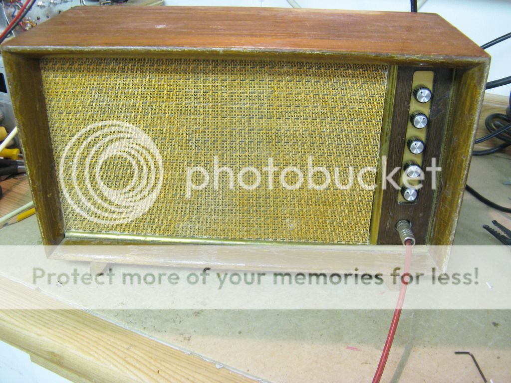
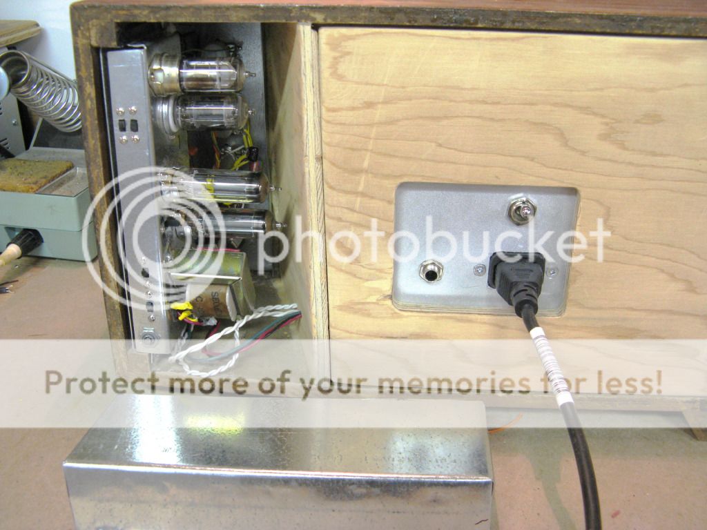
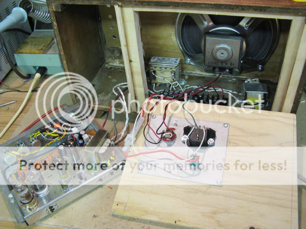
I still have the same two amps I designed for this thread. the whole thing bogged down when I started making the cabinets.
The box for the small amp was first. The plan was for a clear Lexan front plate to make the tubes visible. That was a big mess that ended in frustration. I tried to use spray adhesive to attach the Tolex to the tiny cabined. I now have an ugly box with glue all over it and the Tolex is peeling off in the corners and edges.....
The box for the larger amp is still uncovered. I think I will try the spray on bedliner trick. I have seen speaker boxes made for pickup trucks that were sprayed by a company that does trucks with a paint spray booth. They wanted $75 to spray my tiny box so I walked....
I went to the Orlando hamfest a few weeks ago where I bought 5 dead guitar amps for $5 each. The plan was to gut them and use the cabinets / speakers for these amps. Well the Fender G-DEC Junior intrigued me enough to fix it, now I find myself playing with this little toy. It's kind of a guitar version of a Karaoke machine....cool idea. The Fender Frontman 15, a mid size Crate and a Line 6 stereo head will all be used for their cabinets. I am not interested in fixing them. All have been "tweaked by an expert".
There is a local hamfest for the next two Saturdays, so no amp work will happen. After that, I will finish one of them I promise......Oh yeah.....I put some SAND in the small amp (right in the signal path) and it sounds BETTER.........
They wanted $75 to spray my tiny box so I walked....
LOL. I wonder what they charge for a big box. Yeah, frustrating trying to make an amp look cool with a low budget. I really hate to depend on outsiders to finish my amps. They always want to rip me off. Besides, it's like going to the hairdresser's: you're never sure if they're going to get it right (despite my detailed instructions). Too many morons out there.
So ugly amps for the moment. Some day I will buy proper tools and take my time designing the chassis and maybe, just maybe end up with some kind of professional looking job.
My amp is dead BTW. It didn't deserve to live so I killed it.
I thought this thread had died....I guess not.
I am a little slow.
- Home
- Live Sound
- Instruments and Amps
- The Hundred-Buck Amp Challenge