I would expect the diodes to have at most a marginal effect on current contribution while the amp is operating in ClassA mode.
The diodes would in my opinion only provide significant increases in available current when output current is significantly more than the Max ClassA output.
If the diodes were already passing significant current in ClassA mode then I think you will find that they over-rule the stabilising effect of the source resistor.
Hw did you decide on the value of K and what does it represent?
Hiraga mentions a formula (le classe A)
Pmax = 2Vcc*a)^2
8*Rl
and uses a = 0,85 for bipolars, being the 'collector loss'; with FETS there is also inefficiency in driving, first of all a voltage component (not so much resistance) and there are source resiatances that dominate...
For his amp at 18V+/- he gets 15 watts; his formula at 33 volts this gives 50 watts too! I assume that this K is a similar 'drivability'.
At 3.5A, loss is 1.65v into source resistor let alone .
Diodes should keep about 0.65 volts across that resistor at the same current.
Which is 1volt less.
Diodes should keep about 0.65 volts across that resistor at the same current.
Which is 1volt less.
Last edited:
I too get lost with the introduction of k.
Prior to that K, everything is correct.
...
ClassA output current.
I have assumed the power factor of the linear power supply at the range of 0.6~0.8😱
Shouldn't it be calculate in this way? If its wrong, please point me out😕
peak output voltage level + voltage loss across the drain resistor + voltage to open up the output devices.
(and a little extra )
)
(and a little extra
)where can i buy the f5 turbo PCB s from ?
Just about now, people are discussing few layouts. They are not available to buy from anywhere. You can probably make your own PCB following the layouts discussed here.
Only P3 missing for turbo V1 + one thermistor leg change.
Diodes can be hardwired for V2
Not too bad. Even cascoding is present.
Diodes can be hardwired for V2
Not too bad. Even cascoding is present.
Excellent.. Thanks for the report. Yeah, that's why I mentioned the F-5c. "c" for cascoding. Plus it has 4 output devices rather than the standard two.
If someone does this please post it for all to see! We need the P3 mod shown at a minimum, because that's become the standard F-5 it seems.
If someone does this please post it for all to see! We need the P3 mod shown at a minimum, because that's become the standard F-5 it seems.
Last edited:
About P3, i suggest to hardwire it during tweaking then measure and replace R3 & R4 source resistors by fixed values.
Maybe someone else than me need Layout for V1 😱
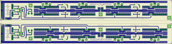
it's single layer with one jumper, mirrored for each channel
Basically its same as my F5 Juma Version 🙂
Hi there
I Like it
did you calculate the track current and temperature rise
I did same for the F5 turbo PCB
Only track worth doing is the speaker out, simplified from most distant mosfet pin to Output therminal 120mm (need lengt of trak for your board)
Taken ambient at 25 c and track temperature rise to 5 and 10 C
for 1 once and 2 ounces copper boards Ambient themperature be the themperature inside case close to sink
Attachments
Is there any chance you guys could start some random chattering, debate, or discussion about this just to give me something to read? I'm studying for medicine and histology exams, and whenever I hit the refresh button no one's said anything since yesterday. I know, strange request from a bleary-eyed student who hasn't had enough sleep...
Austin
Austin
Is this an appropriate place to start talking about part selection, part sourcing, mosfet matching, etc.? If not maybe it's time to start an F5 Turbo builders thread, even though it will be a while before I get boards designed and the thing built. I'm planning a monoblock version with ~+/-48V rails.
I agree that an F5 Turbo builders thread would be useful.
I've already created my BOM's (see my sig).
I was thinking of a 30-0-30 supply which should give about 42-0-42 regulated.
I've already created my BOM's (see my sig).
I was thinking of a 30-0-30 supply which should give about 42-0-42 regulated.
F5 Turbo Builders Thread started here: http://www.diyaudio.com/forums/pass-labs/207103-f5-turbo-builders-thread.html#post2913828
- Status
- Not open for further replies.
- Home
- Amplifiers
- Pass Labs
- F5 Turbo is posted