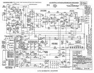
When I look at the D76 schematic below, I see no Van Scoyoc PI in the traditional sense. I see a dual triode input stage and below that another dual triode that does the phase inverting. Next is a cross-coupled stage that, by it's action, supports the phase inversion balance, but does not produce the original inversion. So, are you still calling this a Van Scoyoc? Somewhere I have an artical by a well known author that basically explains what the cross-coupled stage is doing to support the inversion balance. I'll try to find it.Your memory is fine. Go back a little further- D-51, D-76... all with cross coupled inverters.
Attachments
Last edited:
Oh! Crispy Crispies! Holy Something or other Batman! Great Caesars Ghost! (two references to very old TV shows).
I feel so much better now, my dementia is only effecting other parts of my brain! 😀
All my old Audio Research schematics are not on my larftop confuzer...
Back to our regular programming.
_-_-
I feel so much better now, my dementia is only effecting other parts of my brain! 😀
All my old Audio Research schematics are not on my larftop confuzer...
Back to our regular programming.
_-_-
They must have been smoking some really heavy stuff to come up with that D-76 AR schematic. Just looking at the left most tubes, the top signal gets inverted 2 times, and the bottom signal gets inverted 3 times! Then there is the cross coupled stuff. A total of 8 stages! OK, 7 stages, one is a CCS load.
Last edited:
HollowState,
I dunno what to call it exactly, but the question is what would happen if the second stage was driven single endedly? Would it still invert.
The use of the second section of V7 seems like an interesting trick... the "output tube" V9/10 looks like if you put the grids on "ground" (so called) you'd have a grounded grid, and some sort of cascode arrangement. But of course the grids are driven...
Seems like this circuit enforces a balance, but then there is still a balance pot to come in that amp, maybe to correct the differences in the final output tubes, not the incoming signal??
_-_-bear
V7( &8) and V5 (&6) are cathode followers driving cathode followers. WTH for? They must have been getting kickbacks from RCA for selling extra tubes.
Maybe there is some rhyme to the scheme. All four of the inputs to the driver stage are driven by individual cathode followers. The driver then takes the differences. By putting common distortion (from the CF's) on all 4 signals, it cancels in the differences? They must have hired an IC designer.
OOPs, wait a second, that CF driving a CF is a mistake then. They would all have to be coming from the same sources to cancel. NG. Ehh..., the differencing doesn't remove the common distortion anyway it seems. Big mystery what they were thinking here. Hah!, the designer must have gotten paid on a per tube basis in the design or had some phobia to half used tubes.
Last edited:
Next is a cross-coupled stage that, by it's action, supports the phase inversion balance, but does not produce the original inversion. So, are you still calling this a Van Scoyoc?
Yes. You drive the cathode of one side and the grid of the other side from a single point for each polarity. That's as cross-coupled as they get. And yes, overly complicated.
Forbidden
You don't have permission to access /ST70C3/ARC_ST70C3_schematic.gif on this server.
Additionally, a 404 Not Found error was encountered while trying to use an ErrorDocument to handle the request.
You don't have permission to access /ST70C3/ARC_ST70C3_schematic.gif on this server.
Additionally, a 404 Not Found error was encountered while trying to use an ErrorDocument to handle the request.
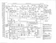
I know that circuit, I have the construction manual. But again, the cross-coupling does not perform the inversion. So we should agree to disagree on the definition of terms with regard to Mr. Van Scoyoc's namesake. You seem to be saying that any cross-coupling is VS. While I was saying it's the inverter in my post pix #489 page 49. The AR cross-coupling stage is but a derivation of VS.Here's a simplified version:
But I will agree that the AR D76 is overly complicated. I think the design goal was a fully balanced differential amplifier from beginning to end without using the traditional VS inverter and still allowing balanced FB with a single ended input. From what I've read, VS style cross-coupling was used to increase gain through positive feedback. These amplifiers would normally oscillate, or be just on the verge, but are kept in check by the local FB from the output tube plates back to the coupler stage. And the cross-coupling also serves to enhance the differential phases. There were other designs that used this theme, but were less complicated. AR just chose to use lots of tubes to get there. Maybe they had copyrite or patent issues to contend with back then. Maybe it was just Bill Johnson gone wild and having fun.
Attachments
Actually the ARC could be looked upon as a paraphase PI but with the amplifiyng stage after the anodefollower😉.
Yes, it is possible to make an amp measure very good and sound like crap.
It's not only possible, it has been the norm for many years. This is what lab equipment has done to many misguided souls.
An externally hosted image should be here but it was not working when we last tested it.
A good "lab monster" will learn to use all his tools to develop a good amp.
Yes. We need more of those. Basically we need more good results and less mumbo-jumbo. My beef probably is only a by-product of all the insanity going around the audio world. People talk too much. Let the amps do the talking.
AR just chose to use lots of tubes to get there. Maybe they had copyrite or patent issues to contend with back then. Maybe it was just Bill Johnson gone wild and having fun.
A few years ago, a small group of tube-o-philes were discussing one of AR's line amps (the LS-22, perhaps?). We could see no logic whatever to the gain structure (too much gain in the first two stages, so two stages with signal loss added after). Many speculations: more tubes= better price justification? Leftover boards from a failed project that had too many tube socket positions in it? Effects box?
It's not only possible, it has been the norm for many years. This is what lab equipment has done to many misguided souls.
I agree that is has been the norm, not only in audio but many other industries. I wouldn't blame the lab equipment as they are just tools. I wouldn't blame the engineers as they are just building to a set of requirements using the tools available.
In the audio industry, and just about every other compettitive market, the marketing department will furnish a requirements document containing specs (electrical, mechanical, and economic). It's up to the engineering department to design to those specs using whatever tools that are needed to get the job done.
It is often the case that the specs given by the marketing department are derived by marketing research that determines what it takes to SELL a certain volume of product in a given market. It often bears NO relationship to how the product actually works.
I have worked in an industry for the last 39 years where the numbers game is just as important as it is in audio. it is not a consumer market, and many customers are government agencies. We engineers are given a set of specs to design a new product. In the early stages of development the marketing department will survey what the competition has, and what it is believed they will have at the time of product launch.
Then they will draw up a spec sheet with better numbers and ask us to design it. Negotiations will take place until we agree on something thay we can actually design and build, AND they can sell. Sometimes the first cut from marketing defies the laws of physics and they have to be reeled back into reality.
If the competition offers a 5 watt product, we will have a 6 watt product even though the fraction of a db means nothing in actual use. The sales guy can convince the purchaser (who may not be the end user, and really doesn't understand the numbers) that 6 is more than 5 and therefore better.
It is exactly the same in mass market audio and always has been. The difference is that any large consumer market can be strongly influenced by TRENDS. You want what your friend has, only better. Back to the numbers game.
The niche market (often known as the lunatic fringe) that we hang out in not a normal market. Proof:
http://www.diyaudio.com/forums/lounge/194219-more-magic-stones-hockey-pucks.html
"Actually the ARC could be looked upon as a paraphase PI but with the amplifiyng stage after the anodefollower"
It (D-76) does start out with an anodefollower then an amplifying stage. It has too much emphasis on symmetrical layout though, I think. The whole reversed PI gets duplicated bottom side, with the top inverted signal sent down to it. What I don't like most is that the global feedbacks come in to the 2nd stage top side and to the "3rd" stage bottom side.
I don't see any positive feedbacks in there, I thought someone mentioned some. Seems to just have a lot of conventional gain. I like the Schade neg. feedbacks to the driver cathodes. Putting in four cathode followers to drive the driver stage is just crazy.
The ARC ST70_C3 looks better.
Last edited:
The niche market (often known as the lunatic fringe) that we hang out in not a normal market. Proof:
More magic stones and hockey pucks
Or more aptly, "Pony pucks," as Col. Sherman T. Potter would say...
Just that the paraphase has a gain stage followed by an inverter stage.
Arc reverses the order with a unity gain anode follower inverter then a gain stage (also inverting). Then duplicates the whole thing for symmetry.
Well, the Arc version does not have equal gain outputs from the unity inverter and gain stage like a paraphase, but their symmetry stuff (or fluff 😱) eventually puts the gain in for matching phases. (after it inverts the signal two more times!)
Last edited:
Steve, see?
We forgot completely about ur amp!
So much for short attention span, eh? 😛
Regards,
_-_-bear
We forgot completely about ur amp!
So much for short attention span, eh? 😛
Regards,
_-_-bear
- Status
- Not open for further replies.
- Home
- Amplifiers
- Tubes / Valves
- Unusual amps..