Safety question
Hello
This might be slightly OT as a general question but as it concerns this build that might be built by many people that like me is not educated in all saftey rules and regulations, I thought it might be proper to ask here. Eventual answer might even serve as a reminder for others.
Regarding a high voltage FET as IRF840 in this case and the outboard placement of the fairly big sink. What is considered enough saftey rearding that? Is it mandatory to place it completely inside and insulated from a grounded metal case or can the sink be touchable from outside the case if both the sink and the case is properly grounded?
Best
Staffan
Read this sticky thread from tubes forum regarding safety. Will link it in post#1 here too.
http://www.diyaudio.com/forums/tubes-valves/30172-safety-practices-general-ultra-high-voltage.html
http://www.diyaudio.com/forums/tubes-valves/30172-safety-practices-general-ultra-high-voltage.html
Read this sticky thread from tubes forum regarding safety. Will link it in post#1 here too.
http://www.diyaudio.com/forums/tubes-valves/30172-safety-practices-general-ultra-high-voltage.html
Yes, thats wise. Its a long and mixed thread with various tips, trix and examples tho and maybe its not self-given for everyone not to mount a HV FET, even with isolation pads so its sink is touchable even if grounded.
When reading I came to #49 that said: "UL specifies a minimum of a 4 mm spacing across a surface (PCB) between any "energized" part up to 400 V Peak and a part of opposite polarity or a "dead metal part" (earth). UL then specifies a 8 mm spacing for any voltage up to, I believe 1000 V peak.
"
I dont know what UL is, some countrys recommendations maybe but I think that clearly specifies that also isolation of the sink from being exposed to small fingers or whatever is mandatory.
Staffan
Yes, thats wise.
Staffan
This one from George is a nice electrical safety writeup also:
Electrical Safety
Salas,
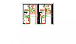
Does this look OK? IT will fir on a standard PCB etch board available here through Radio Shack.
Can't foretell if it will have practical problems. Looks a bit wide loop area for one. Is there no sense/force?
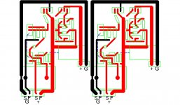
They should be tied at the respective load points after covering the wiring distance. Else you got no ''remote'' but ''local'' sensing. I.e. A classic two wire connection susceptible to wiring length deviations in measuring and counteracting the correct impedance point by the regulator's error amplifier.
Dont have the mounting bar for the heatsink. Left it at the shop. Will not know till Tuesday. After my initial panicked failure first time around, I decided to take things as they come and try to be patient. I work much better this way, and tend to bother forum members less. 😀
Side note. How influential are parts like resistors and caps in tthis circuit?
Side note. How influential are parts like resistors and caps in tthis circuit?
The 10uF capacitors are the most subjectively influential. Then the 0.33uF ones. Lastly the 68K resistors maybe. Better they have good ppm.
What you got now are fine to start. Much better than average. Try such tests you mention after all is well and familiar. Tubes will be the most idiosyncratic by make and vintage.
Cascode CCS "lower" FET dissipation are marginal, not necessary heatsinking.
In my version ( http://www.diyaudio.com/forums/power-supplies/134801-simplistic-mosfet-hv-shunt-regs-263.html ) this position contains DN2540N-3G (TO-92 case).
In my version ( http://www.diyaudio.com/forums/power-supplies/134801-simplistic-mosfet-hv-shunt-regs-263.html ) this position contains DN2540N-3G (TO-92 case).
I never thought about it, but is different wire needed for chassis wire up. I use Radio Shack 20ga.
Cascode CCS "lower" FET dissipation are marginal, not necessary heatsinking.
In my version ( http://www.diyaudio.com/forums/power-supplies/134801-simplistic-mosfet-hv-shunt-regs-263.html ) this position contains DN2540N-3G (TO-92 case).
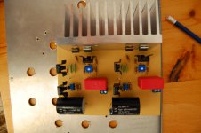
I see different sheen on metal tabs in Buzz's, maybe just Q1 and Q3 on sink per reg in his. Clip-ons for Q2 really not needed.
I see different sheen on metal tabs in Buzz's, maybe just Q1 and Q3 on sink per reg in his. Clip-ons for Q2 really not needed.
Correct. I put one on Q2 because I had ordered extra and it makes it look neat and organized. I found some surplus 20-40 uF GE motor run caps for $6, will be giving them a try.
- Home
- Amplifiers
- Power Supplies
- Simplistic mosFET HV Shunt Regs