
Despite all my bitching I kinda like the guy (we have some points in common). I even like some of his paint jobs.
Oh and 'Shakin' All Over' is a cool song. I didn't know that one.
An externally hosted image should be here but it was not working when we last tested it.
Oh and 'Shakin' All Over' is a cool song. I didn't know that one.
Ok,
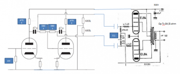
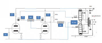
Quick cobble togeather..
So for fun how would we tune this..Is this what we are saying is correct?
Regards
M. Gregg
Quick cobble togeather..
So for fun how would we tune this..Is this what we are saying is correct?
Regards
M. Gregg
Attachments
Last edited:
Doesn't V2 need some kind of bias? Or is there something I'm missing about the 'floating paraphase' circuit, is the grid really floating?
There's some typos in that schematic. There's several ways to "tune" a phase inverter, but first you have to define what the goal of "tuning" is. Best PI balance? Best overall amp balance? Balance over frequency range? Maybe some deliberate imbalance to increase distortion (i.e., amp as effects box)?
There's some typos in that schematic. There's several ways to "tune" a phase inverter, but first you have to define what the goal of "tuning" is. Best PI balance? Best overall amp balance? Balance over frequency range? Maybe some deliberate imbalance to increase distortion (i.e., amp as effects box)?
There is more than a few..LOL
Its just pulled from the thread..2 of this, one of that etc..
But it gives a starting point...ie resistor ? should be ? etc
Also the 680K to Gnd..
Perhaps the answer is to use a pot to balance the PI and then fit standard values?
Regards
M. Gregg
Last edited:
Can put a pot between the 560K resistors, maybe 50K. The extra set of .1 coupling caps are redundant if you can get the output biasing to work out. The 680K's to ground are providing the bias reference for the 2nd P.I. tube, and would also for the output grids if the .1 caps are removed.
The See-Saw variant of the floating paraphase puts a separate ground reference resistor over at the V2 grid, and a cap between the grid and the pot wiper between the 560K resistors. (the 560K's can then go directly to the V1,V2 PI plates.) Then you have separate biasing for the ouputs and V2. (you would want to lift the 680K's center point then to be the output bias V instead of ground)
Alternative descript. of the See-Saw:
remove the 47N caps (jumper across), leave the .1 caps, put a cap from the 560K junction (or the inserted 50K balance pot wiper) down to the V2 grid, then a ground reference resistor from the V2 grid to ground. Remove the 680K resistors since their is a bias network already drawn at the outputs.
Last edited:
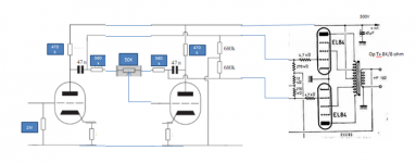
Like this..?
Should have taken the 270K's out of the OP section..
Regards
M. Gregg
Should have taken the 270K's out of the OP section..
Regards
M. Gregg
Attachments
Last edited:
You will need some cathode bias resistors on the EL84's that way since their grids are ground referenced. If you don't want cathode bias there, then convert to the See-Saw configuration. (a cap and resistor for V2's grid, then can lift the 680K midpoint to be -Vbias for the outputs, 560K's then go directly to the floating P.I. plates)
Last edited:
Despite all my bitching I kinda like the guy (we have some points in common). I even like some of his paint jobs.
An externally hosted image should be here but it was not working when we last tested it.
Oh and 'Shakin' All Over' is a cool song. I didn't know that one.
I kinda like the guy too....
You might be too young to remember that one, but it came out in the 60s. I was born in the mid 1960's and grew up with shows like the Addams Family (my all time favourite) which is why my business cards look like they do (you can see one on my website). Any one who watched the show remembers Uncle Fester putting a light bulb in his mouth and making it light up when someone needed some extra light. My cards show me with an 807 in my mouth with a lightning bolt striking to the anode terminal. I got the idea from Uncle Fester. Actually, I was born on this date in 1966.
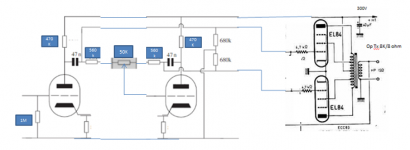
Correction..
I guess a cathode resistor and a bypass cap AKA auto bias..
Regards
M. Gregg
I guess a common/ shared cathode resistor and cap could improve it..
Regards
M. Gregg
Correction..
I assume the PI cathode reistors are at GND?
Guess work cathode resistor values...?? from the thread 2K2..
At this point anybody could print this off and mod then scan and post?
Regards
M. Gregg
I assume the PI cathode reistors are at GND?
Guess work cathode resistor values...?? from the thread 2K2..
At this point anybody could print this off and mod then scan and post?
Regards
M. Gregg
Attachments
Last edited:
MG: There's such high feedback to the second section of the tube that the cathode resistor has only a minor effect on balance. The major parameters are still midband balance between the sections, relative source impedance (and the concomitant imbalance at HF), the different distortion between sections, and the additional LF rolloff in one section. These all interrelate, which is why the target has to be defined before speculating on how to hit it.
If the target is minimum distortion and best balance, you wouldn't use a paraphase.
And Happy Birthday, Steve!
If the target is minimum distortion and best balance, you wouldn't use a paraphase.
And Happy Birthday, Steve!
MG: There's such high feedback to the second section of the tube that the cathode resistor has only a minor effect on balance. The major parameters are still midband balance between the sections, relative source impedance (and the concomitant imbalance at HF), the different distortion between sections, and the additional LF rolloff in one section. These all interrelate, which is why the target has to be defined before speculating on how to hit it.
If the target is minimum distortion and best balance, you wouldn't use a paraphase.
And Happy Birthday, Steve!
OK I'll have to look deeper..(Research)
Thank's
Regards
M. Gregg
Happy Birthday Steve!
"If the target is minimum distortion and best balance, you wouldn't use a paraphase."
For minimum distortion you might try the Full See-Saw!
(Usual diffl. stages have some residual odd harmonic dist., this shouldn't. Of course this IS a diffl. stage but with feedbacks to fix that. Strangely they are positive feedbacks, it's actually what is called "Error Correction" a'la Hawksford)
Full See-Saw:
Just add another dual 560K divider between the plates with a center pot, with the wiper going thru a cap to the V1 grid.
The original pot then gets adjusted for exactly -1 inversion. The new pot gets adjusted for -.99 inversion.
For ultimate low distortion, the 470K pull-up loads would get changed to gyrators, and the dual cathode resistors get combined into a single tail CCS. Have fun adjusting them all though!!
Clearly this would not be a suitable design for a commercial design, since any drift over unity loop gain turns it into an oscillator and it blows out your speakers!!
OH, and the Full See-Saw version has matched output impedances. The ordinary Floating Paraphase or See-Saw has badly mismatched output impedances due to feedback on the second tube only.
Which reminds me, you might want Morgan's build out resistor (like 50K) in series with the V2 output for the standard floating para or See-Saw setup to match the output Z's.
Last edited:
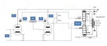
Update..
I would use a mozener in the OP tail..🙂
Just put in the build out resistor..
It would be interesting to have a look at leben PI values..Cassiel posted his thoughts earlier..🙂
I guess some feed back is needed and or gain so more to look at...
Regards
M. Gregg
I would use a mozener in the OP tail..🙂
Just put in the build out resistor..
It would be interesting to have a look at leben PI values..Cassiel posted his thoughts earlier..🙂
I guess some feed back is needed and or gain so more to look at...
Regards
M. Gregg
Attachments
Last edited:
Might be better to put the buildout 50K on the left side of the 680K connection, to avoid any grid current shifts in bias matching.
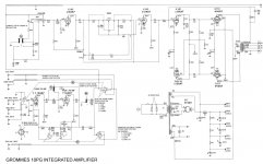
Someone with good monitor color rendition can maybe read off the resistor values from the Leben picture. As Sy mentioned earlier, the plate load R's here (470K) are a bit on the high side.
Someone with good monitor color rendition can maybe read off the resistor values from the Leben picture. As Sy mentioned earlier, the plate load R's here (470K) are a bit on the high side.
Last edited:
Some circuits there Gregg. I have built some of them. Seems Steve has left an impression on you but..... his circuit is probably optimized (no pun intended) for the tubes and parts he had at hand so I wouldn't follow it blindly.
EDIT: It doesn't need to be a high gain tube, I like the 6SN7.
EDIT: It doesn't need to be a high gain tube, I like the 6SN7.
Attachments

Last edited:
- Status
- Not open for further replies.
- Home
- Amplifiers
- Tubes / Valves
- Unusual amps..