Some circuits there Gregg. I have build some of them. Seems Steve has left an impression on you but..... his circuit is probably optimized (no pun intended) for the tubes and parts he had at hand so I wouldn't follow it blindly.
I just find it interesting,
So its got to be worth looking at..curiosity and the cat so to speak..
I wouldnt just follow them..its back to the audiophile tweek approach..
However the Leben has me thinking..🙂
I think the itch is back for a simple el84 amp...
Thanks for the circuits..🙂
Regards
M. Gregg
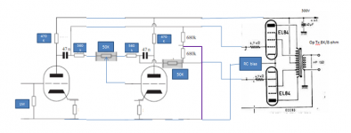
I'm wondering what the sonic advantages are for putting the floating P.I. up first stage versus 2nd stage. I see it both ways in Cassiel's schematics.
All have much lower plate load resistors on the floating P.I. stage. Better drive and bandwidth. Distortion compromised though? I wonder if any recent designs have used gyrator/CCS loads.
All have much lower plate load resistors on the floating P.I. stage. Better drive and bandwidth. Distortion compromised though? I wonder if any recent designs have used gyrator/CCS loads.
Last edited:
Attachments
Some circuits there Gregg. I have built some of them. Seems Steve has left an impression on you but..... his circuit is probably optimized (no pun intended) for the tubes and parts he had at hand so I wouldn't follow it blindly.
EDIT: It doesn't need to be a high gain tube, I like the 6SN7.
I don't use high gain tubes. The only ones I use are 12AU7s, 6C4s, 6SN7s, 6CG7s (electrically the same as a 6SN7 but in a 9 pin format) To me, if you want more gain, add another stage. I think you end up with more detail and an all around nicer sound with better sound-staging. (FYI- now this a bit of me trying to open up and contribute, if you don't agree, don't be unkind. This is me trying to share what I know and do.)
Steve
I think,
its going to take some time to correlate all the information..🙂
Regards
M. Gregg
All have much lower plate load resistors on the floating P.I. stage. Better drive and bandwidth. Distortion compromised though? I wonder if any recent designs have used gyrator/CCS loads.
I think you have already answered the question..With Pi up front you can have a separate driver so the distortion should be better?
Regards
M. Gregg
And Happy Birthday, Steve!
Thanks SY![/QUOTE]
I suppose your out partying...LOL
Happy Birthday..🙂
Regards
M. Gregg
Thanks SY!
I suppose your out partying...LOL
Happy Birthday..🙂
Regards
M. Gregg[/QUOTE]
Thanks, but no, they'll all come here, the music's better!
I can see where the driver stage after the P.I. would allow driving heavier loads (bigger tubes) with low Zout. Not sure of the relative merits on distortion for smaller, easier to drive outputs, say EL84. Maybe Steve or Cassiel have some opinions? Maybe better to have the P.I. on second base if you want high gain up front for noise reasons.
Last edited:
Maybe Steve or Cassiel have some opinions?
If you can get away with one tube why use two - that's my opinion. I never use a lot of negative feedback anyway. And triode wired EL84's sound great with no feedback loop. With bigger output tubes you need two stages.
I can see where the driver stage after the P.I. would allow driving heavier loads (bigger tubes) with low Zout. Not sure of the relative merits on distortion for smaller, easier to drive outputs, say EL84. Maybe Steve or Cassiel have some opinions? Maybe better to have the P.I. on second base if you want high gain up front for noise reasons.
Looking at the info from Cassiel,
It would seem that we don't need the pot for balance. I guess lower value resistors would give a closer tolerance. This is probably irrelevant with modern parts..?
So 100K anode and 1K cathode? No feedback..
Regards
M. Gregg
Last edited:
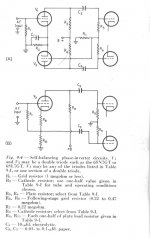
Cathode resistor depends on what current you want the tube to run at. Its the auto bias. Plate resistor depends on B+ available and what load C its gotta drive (slew rate, bandwidth), and also determines linearity of the tube via loading effect.
"It would seem that we don't need the pot for balance."
All depends on how well you want it balanced. For Mu 20 tubes, 5% imbalance without it (unless you build it in with dissimilar divider resistors). How well matched the output tubes are also determines its usefulness. You can use the balance pot to bring mis-matched output tubes back into balance.
Last edited:
Cathode resistor depends on what current you want the tube to run at. Its the auto bias. Plate resistor depends on B+ available and what load C its gotta drive (slew rate, bandwidth), and also determines linearity of the tube via loading effect.
Just off the cuff ball park figures..I notice in the info they are bypassing the first stage cathode with a cap..(Gain)
Also they have the cathodes coupled..😕
Well I might try this for a laugh..😀
I'll wait untill its been chewed over a bit first..
Regards
M. Gregg
Last edited:
I suppose your out partying...LOL
Happy Birthday..🙂
In Steve's part of the country it's only 11am. Out here on the west coast, it's 8am. Won't be beer time here for at least another hour. 😉
In Steve's part of the country it's only 11am. Out here on the west coast, it's 8am. Won't be beer time here for at least another hour. 😉
4.00 aft here it's a bit early.. 😀
Regards
M. Gregg
- Status
- Not open for further replies.
- Home
- Amplifiers
- Tubes / Valves
- Unusual amps..