I will have to try out your idea. One problem for me though is that my Class-D amps are the most transparent and clear of all the amps I have. I am expecting a Decware SE84 and it might be transparent enough to judge the effect of an output filter.
The Audio Research 150.2 amp arrived and I have compared it to my amp. The Audio Research Amp is a Class-D amp just like my DIY amp. Audio Research is one of the oldest and most respected high end manuf. The amp has gotten rave reviews from nearly everyone who has reviewed it; the most common comments are that it is very neutral, has a large sound stage, is "tube like", and is smooth sounding. The AR retailed for $3,000 in 2004.
After I hooked the AR up, I immediately turned it up as loud as I've been listening to my DIY amp. It was obvious right away, I don't like the AR amp. It is edgy in the highs and surprisingly, vocals are harsh when someone shouts, which is one of my pet peeves. Those are the things that are deal breakers for me. The AR has more sibilance than mine (too much for my taste). Another difference is that my amp has more extreme highs than the AR, some have commented that the AR is "polite", and my amp probably is still a bit too hot in the extreme highs. My amp has a larger sound stage, mostly because it's sound is light weight in the low midrange compared to the AR, but I could change that as you know. Ambience comes through more clearly, on my amp. My amp is also light weight in the bass compared to the AR, but I can also adjust that too. The AR has a very high input impedance, 150,000 ohms, and Sure DIY amps have a low input impedance. That hasn't been a problem for me yet. I haven't tested it, but the AR amp will probably sound better on 8 ohm speakers since I designed my amp specifically for my 4.6 ohm speakers. Another advantage the AR has is that it is about three times more powerful than my amp. However, to prove to myself that my amp is capable of driving my low sensitivity speakers, I turned the sound up till the loud parts hurt my ears and it stayed clean.
I know for sure now that I am on the right track
I am a truly happy person.
James
I also want to add that there is nothing special about my DIY amp. All I have done is match the output filter to my speakers, tweaked the sound to my preferences and put PIO caps in place of the input caps. That's all. I honestly think I could take any other DIY amp on this forum and it would equal or be better than my amp and the AR amp, or I could tweak it to my ear so it was.
I also don't think that matching your output filter to your speakers is anything magic. You can get just as good results with the conventional approach. I did however find my DIY amp easier to tweak (the sound) with the matched output filter in place.
I also don't think that matching your output filter to your speakers is anything magic. You can get just as good results with the conventional approach. I did however find my DIY amp easier to tweak (the sound) with the matched output filter in place.
James i copied my results as you asked in your thread here .
Finished modding the sure board 2*100 TK2050 for 4ohm loads.
So here it is : Zobel 0.47uf - 10 ohm.
The rest capacitors on the output are 0.47uf . The differential mode capacitor was changed to 0.22uf instead of 0.1uf . The funny thing here is that in the beginning i used wima mkp4 caps (sound was ok) then changed them with with ero mkt1822 (not so good) & then i used RIFA PHE426 & the sound is amazing, very high end i may say. I changed the inductors with 10u ones. I put 1 2200uf (also 1000uf works fine)nichicon muse cap per channel & 2 panasonic fc 470uf at the 5v rail.
And the most imroved thing to do is disconnect the fan and supply it with an external power supply ( i used a modile phone charger with on/off switch), that worked great. Input caps are 2.2uf ERO MKC1862 (rare polycarbonate) bypassed with mkp1837 33nf.
This is it James. Sure board now is one of my favourites BUT YOU NEED TO SPEND SOME MONEY & TIME ON IT !!!
Now i will deal with the T2 from HiFimeDIY !!!
Will post pictures soon.
Here's a neat online RLC calculator that gives a results graph......
RLC Low-Pass Filter Design Tool
Don't forget we're trying to shoot for adequate attenuation at the switching frequency as well. This isn't a HAM forum; let's not build radio transmitters.
RLC Low-Pass Filter Design Tool
Don't forget we're trying to shoot for adequate attenuation at the switching frequency as well. This isn't a HAM forum; let's not build radio transmitters.
Here's a neat online RLC calculator that gives a results graph......
RLC Low-Pass Filter Design Tool
Don't forget we're trying to shoot for adequate attenuation at the switching frequency as well. This isn't a HAM forum; let's not build radio transmitters.
Thank you so much! Do you know what an approproate range of corner frequencies, and highest acceptable frequency, would be for adequate suppression at the switching frequencies of TK2050s?
I know what you mean. I have spent hours playing with those values and changing to a lower value capacitor usually results in mor peaking with the conventional output filter.I put my zobel back to 0.22uF 10 Ohms . In the end I felt like the highs became too weirdo with 0.1uF as Cz.
jyoung
Take a look here
Remember though, if you don't also calculate, then change the output filter itself, then changing just the zobel to the calculated values will probably only make things sound worse.
In the conventional output filter, what everyone is using on class-d, the zobel is deliberately not matched to the speakers, but is used to control the peak or rolloff that results when the amp is used with a range of speaker impedances. When the output filter is correctly designed, so the filter and zobel work together, then there is very little change in response when going from 4 ohm to 8 ohm speakers. As shown in Mr. Marshals tutorial.
What we want to do here is match our amp exactly to our speakers. This gives us a much flatter response to start from for tweaking to our liking.
About the mids said:I though about what you said, and have couple of questions.
Can I use passive 1st order low pass filter before amp and totaly get rid of output filter?
I gues I can if its filter out swiching frequency of 650Mh at least as good as second order output filter.
For now I run my midrange just with 0.1uf input cap to filter out lows. But it could cross better with planar tweeter at 7000-10000hz and not running full range
Here is some simulations:
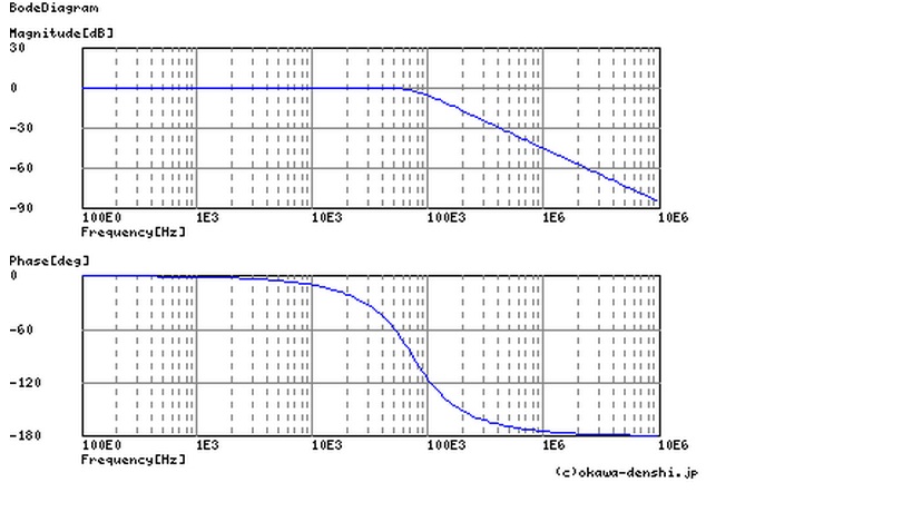
This is standart output of hifimediy t1, t2 amp with 10uh coils and 0,47uf caps wich gives corner frequency of 73,4 kHz and filters out about 37db at 650MHz.
http://content22-foto.inbox.lv/albums184495701/roxis86/12-11-2011/1st-order-passive-input-filter.jpg
Simulation of 1st order lowpass at amps input, Cut-off frequency 7234Hz, filters -40db at 650MHz.
Can I use passive 1st order low pass filter before amp and totaly get rid of output filter?
I gues I can if its filter out swiching frequency of 650Mh at least as good as second order output filter.
I am fairly sure that you can't do that, no.
There is a significant amount of rather high-power radio-frequency signal present on the unfiltered output. This high-frequency component is created in the amp, and is an unavoidable side-effect in a Class-D amplifier. This signal is not present on the input side, so it can't be filtered there.
This high-frequency signal will A) radiate from the speaker wires and can interfere with any electronics nearby, and B) the not insignificant 600KHz signal will also go through the speaker voice coil and may fry your speaker, and most certainly create audible distortion.
I am fully aware of swiching noise at output.
I gues jyoung idea was that it is possible to use second order or greater analog low pass at amps font using the same corner frequency you would use as output filter. It could allready be benefit to use filter at small levels without inductors.
My idea was using input filter as x-over for midrange and at the same time filter would filter out this unwanted high-frequency component.
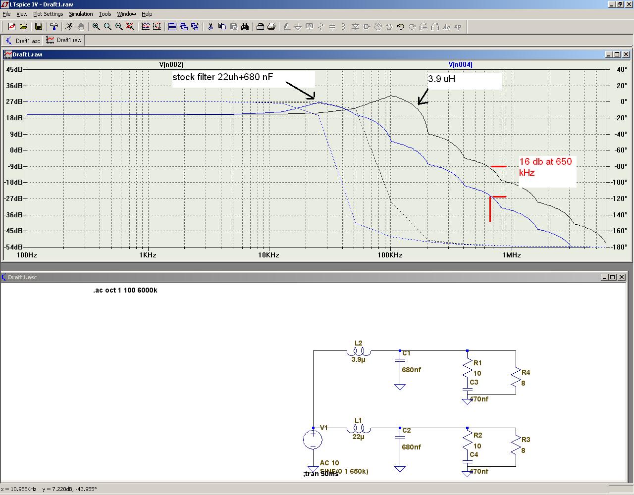
Using simulations you can see that even 1st order at 7000Hz filters this unwanted high-frequency signal better than 2nd order at 73000Hz.
I this graph you can see that Sure amps output filters even less than that, only 27db!
Sendler an many others even prefer output with 3.9uf inductors and only - 17db filtering!
But your point is that filter must be on output. Maybe there is some tehnical explanation of this wich I dont know?
And jyoung070848, did you tried this or this statement was theoretical?
I gues jyoung idea was that it is possible to use second order or greater analog low pass at amps font using the same corner frequency you would use as output filter. It could allready be benefit to use filter at small levels without inductors.
My idea was using input filter as x-over for midrange and at the same time filter would filter out this unwanted high-frequency component.
Using simulations you can see that even 1st order at 7000Hz filters this unwanted high-frequency signal better than 2nd order at 73000Hz.
I this graph you can see that Sure amps output filters even less than that, only 27db!
Sendler an many others even prefer output with 3.9uf inductors and only - 17db filtering!
But your point is that filter must be on output. Maybe there is some tehnical explanation of this wich I dont know?
And jyoung070848, did you tried this or this statement was theoretical?
I am fully aware of swiching noise at output.
I gues jyoung idea was that it is possible to use second order or greater analog low pass at amps font using the same corner frequency you would use as output filter. It could allready be benefit to use filter at small levels without inductors.
My idea was using input filter as x-over for midrange and at the same time filter would filter out this unwanted high-frequency component.
Using simulations you can see that even 1st order at 7000Hz filters this unwanted high-frequency signal better than 2nd order at 73000Hz.
I this graph you can see that Sure amps output filters even less than that, only 27db!
Sendler an many others even prefer output with 3.9uf inductors and only - 17db filtering!
But your point is that filter must be on output. Maybe there is some tehnical explanation of this wich I dont know?
And jyoung070848, did you tried this or this statement was theoretical?
Here is the graph:

But your point is that filter must be on output. Maybe there is some tehnical explanation of this wich I dont know?
Class-D amplifier - Wikipedia, the free encyclopedia
www.irf.com/technical-info/appnotes/an-1071.pdf
www.analog.com/library/analogDialogue/archives/40-06/class_d.pdf
www.national.com/assets/en/appnotes/ClassDAmplifierFAQ.pdf
www.ti.com/lit/an/sloa031/sloa031.pdf
Last edited:
Sorry Lenta but you should never eliminate the filter after the amp because you would be broadcasting nasty stuff. A filter befor the amp won't work to stop that. I'm sorry if you thought that I suggested that.
James :-(
James :-(
I am sorry to report that I made an error in my instructions for calculating the output filter values for a BTL output. I did say I am new at this and no one caught me in the error. Still no excuse! I'm going to crawl under a rock now and never come out.
Before I do I am going to give you the correct instructions.
Measure the DC Resistance and Voice Coil Inductance of your tweeter (or look it up in the manuf docs).
Then choose one of the standard output inductors and use the following equation to see if the corner frequency of the filter will be acceptable. If your output is single ended, use the actual value of the speaker resistance, If your output filter is BTL, DIVIDE THE SPEAKER RESISTANCE BY 2. You can try your current inductor's value to see if you can keep it.
fse=1000*(0.2251*Rs)/Lf
fbtl=1000*(0.2251*0.5*Rs)/Lf
Remember to change the value of the inductor from uH to mH before putting it into this equation, then change it back to uH to get the final value. If the cutoff freq is more than 35,000Hz you can keep the inductor, and not too high (I don't know yet what too high is).
Then solve for C:
For Single ended filters:
Cse=1000000*(0.1125/(Rs*fse))
For BTL filters:
Cbtl=1000000*(0.1125/(0.5*Rs*fbtl))
This will give you the capacitor for the output filter (not the zobel, don't confuse the two).
Zobel:
For the zobel you can use any online zobel calculator such as:
http://www.carstereo.com/help/Articles.cfm?id=36
Just plug in your tweeter's DC Resistance and Inductance (in mH)
This means that for 4 ohm speakers an inductor value of 15uH or even 10uH (you can keep the inductors on the Sure boards) will work, but 33uH as I suggested in the beginning WILL NOT WORK. 33uH produces too low a cutoff frequency.
I checked my work on the RLC Calculator that theAnonymous1 provided and it seems to confirm that the above method works properly.
I sincerely apologize to everyone, especially to you Vassilis.
James :-(
I've discovered why my Class-D amp sounded better to me than the Audio Research 150.2. I isn't that there is anything wrong with the AR of course. The AR amp is described as "polite". My speakers are also polite, the combination resulting in revealing the natural harshness of strings and voices in the 2,000hz to 8,000hz range. The AR amp will sound fantastic with slightly bright speakers.
James
James
I tested the new calculations on my amp and the sound was slightly dull, probably because the 4.6ohm value for my speakers is too high. I wasn't able to directly measure the DC resistance of my tweeters because the manuf must have blocked DC since this is a ribbon speaker. I am experimenting with raising the resistance in the zobel or lowering the capacitance in the output filter.
About the mids, I haven't given enough thought to all the ramifications of output filters for mids. Again, hazarding a guess, the effect of the output filter is high enough that it probably won't have a great effect on your results. Also, if you are using a second order or greater analog low pass, or greater, on your mid, and if you moved the filter to immediately after the amp, you should be able to get rid of the entire output filter and zobel, since all the output filter does is get rid of the switching frequency and the mid, and woofer too, low pass will do that for you. You don't want the switching frequency running down the speaker wires, hence the move of the filter. If you are using an active system, I think it might be best to leave the output filter in since the switching frequency messes with electronics.
James then I didnt understand your quote about eliminatig output filter?
What I was trying to say, not very effectively, is that if you are using a filter before your amp, you can calculate the standard analog speaker filter that is equivalent to your pre-amp filter and putting the analog filter after the amp, replacing your output filter and eliminating one filter from your path. The standard analog speaker filter will do the job of filtering out the switching frequency (but it has to be after the amp and as close to the amp as possible) if it is second order or greater. I suppose a first order filter might work if it is low enough in cutoff frequency, but that would be for someone who knows more thanI to confirm. I you are using a digital filter before your amp, the advantage of eliminating one filter would have to overcome the advantage of using the digital filter PLUS the output filter for this to be of value.
Sorry for misleading you
James :-(
Sorry for misleading you
James :-(
Perhaps the misunderstanding is that it is perhaps possible to eliminate the zobel, which is part of the overall output filter... ?
- Status
- Not open for further replies.
- Home
- Amplifiers
- Class D
- Match Your Output Filter to Your Speakers - All Boards Welcome