carlosfm explains cartridge loading here:
Oh dear, just another post of this kind. One should really think cartrdige loading should be well known by now.
It is beyond me how one can simulate the electrical parameters and neglect fully the mechanical properties of the stylus itself. Most cartridges have a mechanical resonance at high frequencies (overshoot) that helps to keep the frequency response up. The termination then brings that down somewhat.
Simulating only the electrical part of the cartridge does not give meaningful results.
Some also like to simulate MC-impedances and show perfectly flat frequency responses. However, looking at the accompanying measured frequency response it is nowhere close to flat (at high frequencies).
Say, if the manufacturer of an MM cartridge recommended 10Kohm impedance loading, you would probably not buy that cartridge, because it's not compatible with your MM phono pre, right?
Some cartridges, I think Shure V15 III?, had recommendations for 100k. There is no point in loading an MM cartridge with such a low input impedance (10k) due to its high internal resistance.
47k is a compromise as is everything, increasing it to 100k might give good results (check with scope! It's exact behaviour is hard to predict), but remember 100k will add twice the noise.
The previous blank statements on termination lack any technical foundation. It might work for him exactly this way, but certainly not for every cartridge.
Hannes
Have now spent a couple of days finding the parts. Just want to double check that i've got the ideal parts listed now. (i realise that things like the tone controls, low/high cut and loudness aren't often used)
Remaining Electrolytic caps
C134 & C135 - Mundorf M-lytic AG 15,000uF 63V
C201a/b - Nichicon Muse KZ 47uF 25V
C204a/b - Elna Silmic II 22uF 16V
C302a/b - Panasonic ECE 0.33uF 16V (can get Nichicon FG to match rest but more difficult to find)
Mylar Caps
C105a/b & C114a/b - 56nF LCR MKPHR Polystyrene 63V DC
C106a/b - 1.5nF Vishay MKP1830 Polypropylene 100V DC
C115a/b - 5.6nF Polystyrene 630V DC
C116a/b & C127a/b - 47nF Vishay MKP1837 Polypropylene 100V DC
C119a/b - 2.7nF LCR FSC Polystyrene 160V
C124a/b & C125a/b - 2.2nF Polystyrene 630V DC
C126a/b - 1nF Polystyrene 630V DC
C202a/b - 6.8nF Polystyrene 630V DC
C203a/b - 39nF Polystyrene 630V DC
C206a/b - 56nF LCR MKPHR Polystyrene 63V DC
C207a/b - 270nF Panasonic ECWF(A) Polypropylene 250V DC
Ceramic Caps
C123a/b - 5pF Silver Mica 500V DC +/-5%
C205a/b - 560pF Polystyrene 630V DC
Rectifying Diodes - Suggested replacement was MUR820, but the TO-220 shape won't fit the amp so I found these:
D115-118 - Turbo2 rectifier STTH5L06 5A 600V <---The originals are S3V20. Would they be suitable?
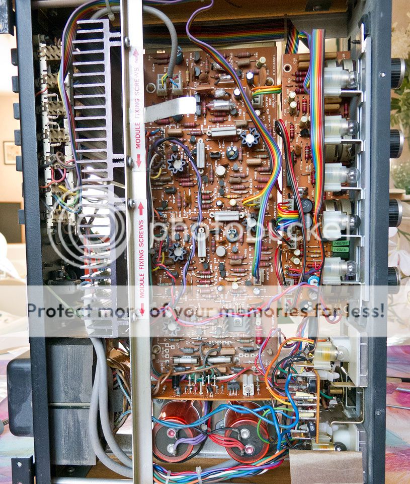
I have found a source that seems to be able to supply everything as polystyrene using suflex and LCR parts if that's a better bet vs mixing components as above. (irony has it, i live just minutes away from the manufacturing plants for both LCR & Suflex. I think suflex closed down though.) I've decided to stick with my original plan of replacing all the carbon based resistors with Takman REY25 metal film. (was looking at arcol & welwyn but they had to be bought in batches of 5 which pushed the cost up. The holco's would have been too big to fit nicely.) There is a gallery of the inside of the amp here if it helps.
Remaining Electrolytic caps
C134 & C135 - Mundorf M-lytic AG 15,000uF 63V
C201a/b - Nichicon Muse KZ 47uF 25V
C204a/b - Elna Silmic II 22uF 16V
C302a/b - Panasonic ECE 0.33uF 16V (can get Nichicon FG to match rest but more difficult to find)
Mylar Caps
C105a/b & C114a/b - 56nF LCR MKPHR Polystyrene 63V DC
C106a/b - 1.5nF Vishay MKP1830 Polypropylene 100V DC
C115a/b - 5.6nF Polystyrene 630V DC
C116a/b & C127a/b - 47nF Vishay MKP1837 Polypropylene 100V DC
C119a/b - 2.7nF LCR FSC Polystyrene 160V
C124a/b & C125a/b - 2.2nF Polystyrene 630V DC
C126a/b - 1nF Polystyrene 630V DC
C202a/b - 6.8nF Polystyrene 630V DC
C203a/b - 39nF Polystyrene 630V DC
C206a/b - 56nF LCR MKPHR Polystyrene 63V DC
C207a/b - 270nF Panasonic ECWF(A) Polypropylene 250V DC
Ceramic Caps
C123a/b - 5pF Silver Mica 500V DC +/-5%
C205a/b - 560pF Polystyrene 630V DC
Rectifying Diodes - Suggested replacement was MUR820, but the TO-220 shape won't fit the amp so I found these:
D115-118 - Turbo2 rectifier STTH5L06 5A 600V <---The originals are S3V20. Would they be suitable?
I have found a source that seems to be able to supply everything as polystyrene using suflex and LCR parts if that's a better bet vs mixing components as above. (irony has it, i live just minutes away from the manufacturing plants for both LCR & Suflex. I think suflex closed down though.) I've decided to stick with my original plan of replacing all the carbon based resistors with Takman REY25 metal film. (was looking at arcol & welwyn but they had to be bought in batches of 5 which pushed the cost up. The holco's would have been too big to fit nicely.) There is a gallery of the inside of the amp here if it helps.
Those diodes seem OK.
As long as the caps physically fit OK and are the correct values then there should be no problems.
Must admit I'm not really a "believer" in expensive boutique parts, good quality commercial yes. But that's just me, you go for it 😉
As long as the caps physically fit OK and are the correct values then there should be no problems.
Must admit I'm not really a "believer" in expensive boutique parts, good quality commercial yes. But that's just me, you go for it 😉
I'm sceptical about it myself but I have never done anything like this before so it'll be fun to see if i can hear any difference. There was a very subtle difference after changing the majority of the electrolytics. (but i reckon that was down to the fact that 2 of the old caps were well knackered, one was totally dead and the other was miles out) I'll also be swapping out C301a/b, C118a/b and C104a/b for polypropylene film which should yield a minor improvement over the electrolytic originals. (changing C301 to film should make C302 redundant from what i've been told)
I could make it sound worse, as i'm reasonably content with the sound as it is.
One thing i have noticed is the hilberink luxman site has been updated with this...
With the ceramic bypass caps mentioned, should they be multilayer or single and is there any particular type of dielectric that is optimum? (X7E, Z5U for multi and E, F for single)
I could make it sound worse, as i'm reasonably content with the sound as it is.
One thing i have noticed is the hilberink luxman site has been updated with this...
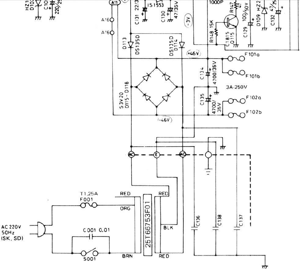
It doesn't really go into details as to how. I can't quite see how its possible.The power supply main capacitors C134, C135 of 10000 uF (4700 uF in L200) need to be decoupled by small HF capacitors:
add 2x 0,01 uF 100V ceramic, parallel to C134 and C135.
You can separate the power supply section to the main amps:
add 4 diodes capable of 6 Amperes continuous current, add 2 main caps of 10000 uF (4700 for the L200) (plus decoupling caps of course). Now you can have 2 separate power rails for the 2 power amps.
With the ceramic bypass caps mentioned, should they be multilayer or single and is there any particular type of dielectric that is optimum? (X7E, Z5U for multi and E, F for single)
To start splitting the rails is really hacking it about, cutting print and so on. It means duplicating the PSU section and separating the supplies to each power amp feeding one off the "new" additional supply. Madness 🙂
Adding further decoupling across rails can sometimes be worthwhile but again there can be hidden problems. It can be better to have a small non inductive (carbon/metal) resistor of say 1 or 2.2 ohms in series with the 0.1uf caps. It all depends on what noise is present. If there is "spiky" HF noise present then adding a cap on its own can cause problems as it interacts with any inductance of the print/wiring etc and could in some cases make things worse. The resistor stops that problem and still allows a low impedance at HF. The only source of "noise" in this amp is from the diode bridge as the diodes come into and out of conduction.
Adding further decoupling across rails can sometimes be worthwhile but again there can be hidden problems. It can be better to have a small non inductive (carbon/metal) resistor of say 1 or 2.2 ohms in series with the 0.1uf caps. It all depends on what noise is present. If there is "spiky" HF noise present then adding a cap on its own can cause problems as it interacts with any inductance of the print/wiring etc and could in some cases make things worse. The resistor stops that problem and still allows a low impedance at HF. The only source of "noise" in this amp is from the diode bridge as the diodes come into and out of conduction.
Presumably the only real way to measure the noise and any changes would be with a scope which is the one tool i lack. I wasn't planning on making any major changes to the psu, and i know that splitting the rails is beyond my present skill so I'll leave that alone.
I assume the resistors in series with the extra decoupling caps would be a good idea regardless. Fingers crossed then this should be the last component for my list. How many watts should it be?
I assume the resistors in series with the extra decoupling caps would be a good idea regardless. Fingers crossed then this should be the last component for my list. How many watts should it be?
Resistors can be 1/4 watt for this.
One thing I would consider even with replacing the diode bridge is perhaps to add something like a 0.1uf + 2.2 ohm across each winding of the mains transformer at the bridge rectifier end. For that particular application you would need suitably rated rated caps (0.1uf mains class x or y would be as good as any) and use 1 watt resistors.
One thing I would consider even with replacing the diode bridge is perhaps to add something like a 0.1uf + 2.2 ohm across each winding of the mains transformer at the bridge rectifier end. For that particular application you would need suitably rated rated caps (0.1uf mains class x or y would be as good as any) and use 1 watt resistors.
Assume you mean something like this

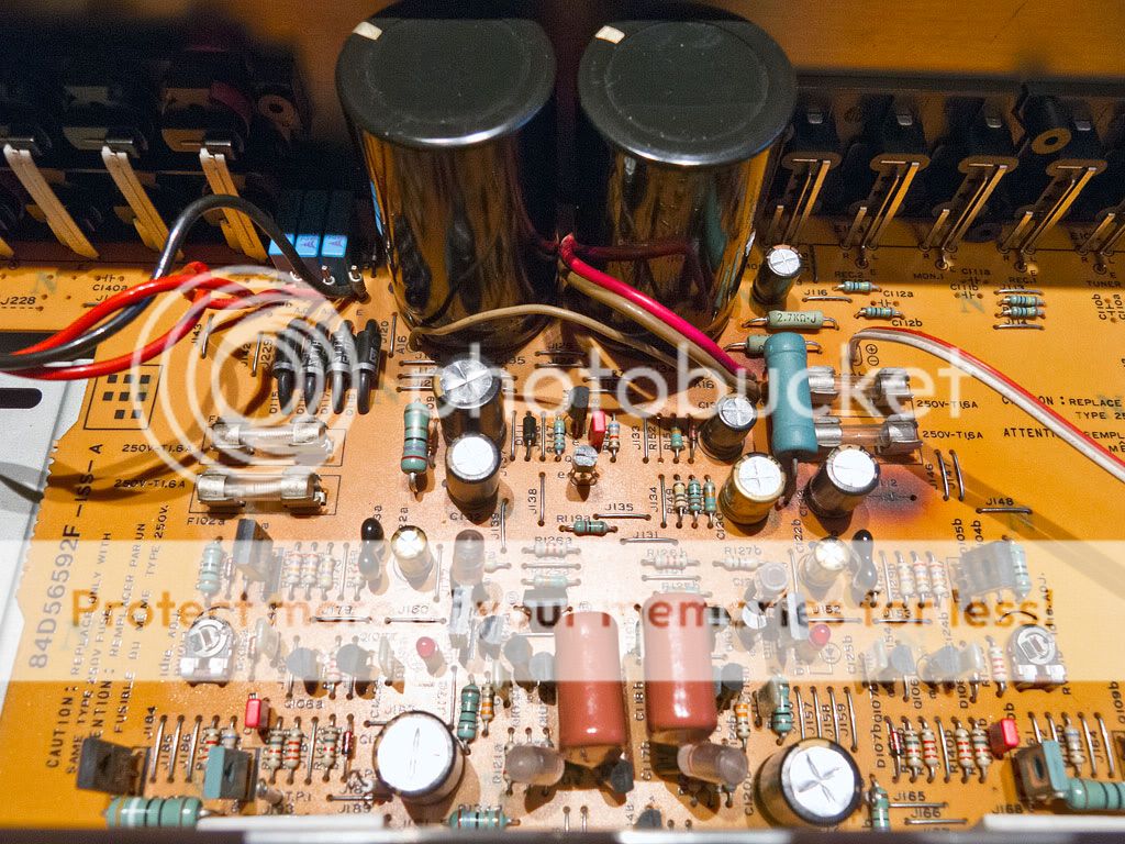
This is the diode bridge in the amp. There are 3 empty cap locations next to the other pair of diodes. These aren't marked in the circuit diagram.
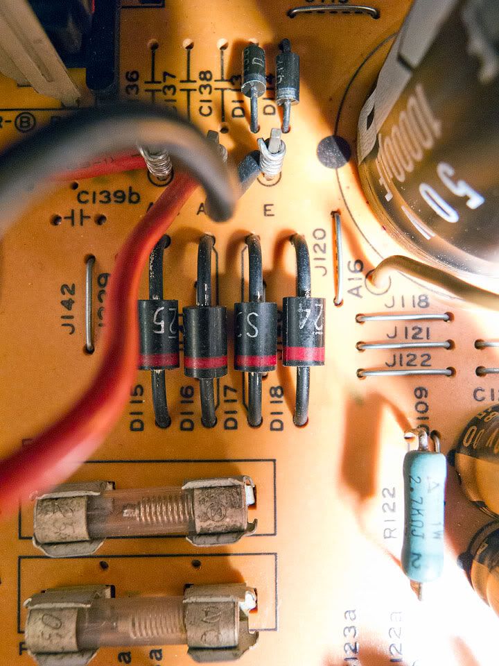
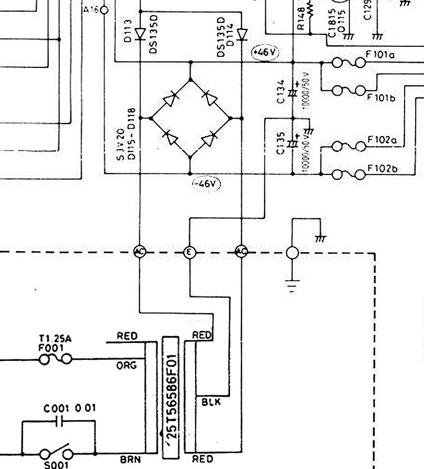
This is the part of the schematic (not sure where they'd go)
EDIT: found where those 3 caps go. They are 10nF ceramic. (L215/235 has them in the german market SD models)
This is the diode bridge in the amp. There are 3 empty cap locations next to the other pair of diodes. These aren't marked in the circuit diagram.
This is the part of the schematic (not sure where they'd go)
EDIT: found where those 3 caps go. They are 10nF ceramic. (L215/235 has them in the german market SD models)
Last edited:
Assume you mean something like this
An externally hosted image should be here but it was not working when we last tested it.
Can't edit my daft mistake out now. Wasn't really thinking properly when i posted that. I know what you meant by in series, i'm not quite as dumb as i've made myself appear.
🙂 You can actually get "snubber caps" that have a series resistor built in but they are around the 100 ohm value... bit too high.
Those 3 caps are essentially the same idea. There's no right and wrong way to this. Three caps like you show or two caps and series resistors or just one cap and resistor across the two secondary outputs. All try achieve the same result. The series resistor approach has become more popular lately for just adding a filter that hopeful will work with "any" noise that may come along.
If you have a specific noise issue you can design a specific filter for it.
Got some of the components through over the last few days. Sorted out a majority of the signal path resistors, the riaa op-amp, a few of the remaining electrolytic caps and some of the new film caps. The difference in sound already is actually quite surprising. The low-end has really picked up a lot. The mids and highs don't sound particularly different perhaps "slightly" more detailed but not a big difference like the LF. The change in the riaa was huge (probably down to the op-amp) the brightness and sibilance is gone and it sounds almost perfect already. (even without the rest of the new film caps which I'm waiting for.) I found some mistakes in the service manual as well. C202a/b are 4.7uF not 47uF.
Some pictures for those interested.
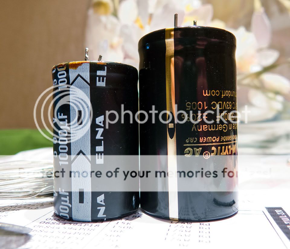
New vs old PSU filter caps

New vs old rectifying diodes

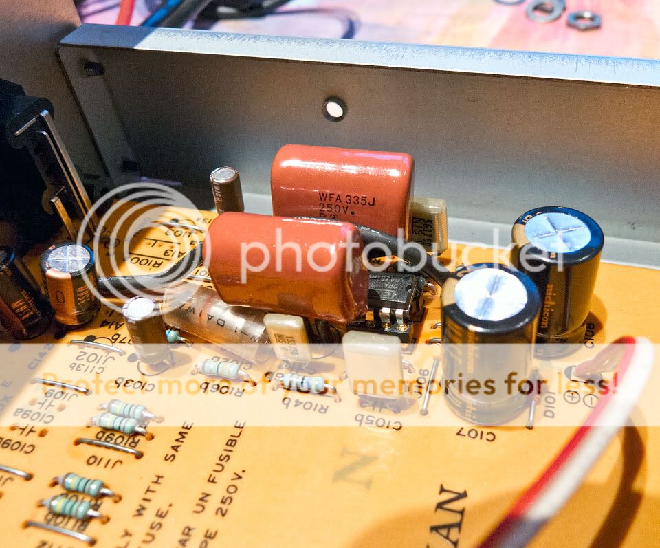
Main filter cap decoupling (EPCOS 305Vac 100nF were supposed to be those wima FKP 100v 1nF caps but they were way too small)

Transformer decoupling, left out the series resistors for now (can't think of a way to fit them neatly)
RIAA, BurrBrown OPA2134 fitted via a nice socket. 3.3uF electrolytic caps replaced with panasonic ecwf polypropylene. (rather large)
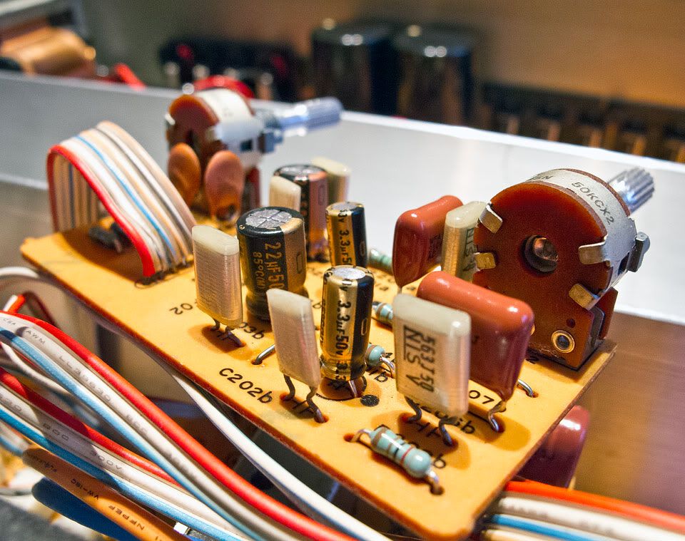
Amp, New Wima FKP caps in place, the silver mica in place of the old ceramic and some of the metal film resistors. Not sure if i'm going to go the whole lot on the resistors. Another pair of panasonics in place of the original electrolytic caps too.

Switches, All metal film resistors done and vishay MKP1837 in place. (not the neatest here due to their size)

Function switch, all electrolytic caps replaced with PP film.
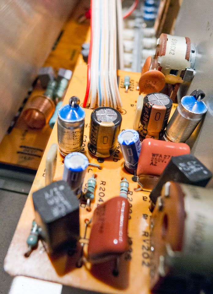
Tone control, two of the film caps done (smaller for a change) and all of the resistors done.
Some pictures for those interested.
New vs old PSU filter caps
New vs old rectifying diodes
Main filter cap decoupling (EPCOS 305Vac 100nF were supposed to be those wima FKP 100v 1nF caps but they were way too small)
Transformer decoupling, left out the series resistors for now (can't think of a way to fit them neatly)
RIAA, BurrBrown OPA2134 fitted via a nice socket. 3.3uF electrolytic caps replaced with panasonic ecwf polypropylene. (rather large)
Amp, New Wima FKP caps in place, the silver mica in place of the old ceramic and some of the metal film resistors. Not sure if i'm going to go the whole lot on the resistors. Another pair of panasonics in place of the original electrolytic caps too.
Switches, All metal film resistors done and vishay MKP1837 in place. (not the neatest here due to their size)
Function switch, all electrolytic caps replaced with PP film.
Tone control, two of the film caps done (smaller for a change) and all of the resistors done.
Thanks for the update (and piccys).
I thought the opamp would make a big difference and with a socket you can always evaluate others too. Always best to listen for quite a few days I find if you try anything like that as your expectations often get in the way.
I thought the opamp would make a big difference and with a socket you can always evaluate others too. Always best to listen for quite a few days I find if you try anything like that as your expectations often get in the way.
I've being testing it every couple of changes to make sure I haven't done anything wrong. (or a new component not working properly so it can be found easily) The biggest differences have been the opamp and the large filter caps. Those film caps i did today made next to no difference. (that i can hear at least)
The polystyrene capacitors finally turned up today (been waiting since mid january), so i got straight to fitting them. They are slightly big but fit OK in most of the locations. Upon listening, i believe that there is a slight audible difference. There is one substantial difference i have noticed and that is the crosstalk between inputs has disappeared completely. The phono stage is sounding very nice now which i am extremely pleased about.


One problem i have created is the treble tone control no longer works properly, it causes the left channel volume to increase/decrease when the tone control is enabled (rather than defeated) The bass control works as it should and the right channel is unaffected. What have i done?
One problem i have created is the treble tone control no longer works properly, it causes the left channel volume to increase/decrease when the tone control is enabled (rather than defeated) The bass control works as it should and the right channel is unaffected. What have i done?
Check for any components shorting or touching something. In that last pic a cap looks to be forced into contact with the chassis.
Was wondering whether that might potentially be the cause. I know that the problem lies with an A channel cap. (which that one is) I'll swap the muse cap out for a smaller rubycon which will give me some more space to work with.
Done and fixed, must have been that axial cap touching the chassis. I'll look into replacing the old rubycons with something smaller than the nichicon KZ. (only needed 16v caps and they were 50v)
Finally finished the remainder of the work on the Luxman, the last of the caps in the tone control. I used some more styrols in place of film/ceramic and some panasonic FC to replace the old rubycons. (moved away from all the "audiophile caps" as they really don't sound any better and their ratings aren't as good, so i'm using panasonic FC/FM/FR and rubycon ZL/ZLH/ZLG/ZLJ instead as they will last longer, withstand higher temperatures, have lower ESR and most importantly they cost far less.) I also had a go at swapping the RIAA opamp out for several others that i had. Gave both OPA2604 and LM4562 a go, but found myself preferring the OPA2134 that i took out as the others whilst sounding ever so slightly "sweeter" increased the sharpness and sibilance a tad. Going to look into getting some samples so i can try out a few more if anyone has any suggestions. I also built up an LED board for the front panel lights which now works nicely albeit quite dimly due to the LED's i used. The addition of the lights also got the muting circuit to work properly too.


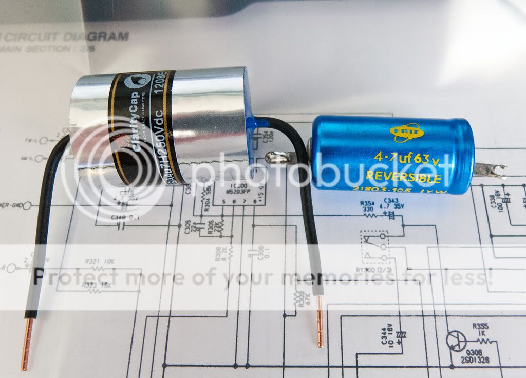
Also got around to sorting out my crossover capacitors in my speakers. Put in some clarity cap ESA's to replace the mid 70's bipolar electrolytics. Will probably fit some new crossovers as the originals just float in the cabinet and are quite crude. (since my speakers are in essence Kef Chroales in goodmans cabinets, I'm looking into making up the chorale crossover from Falcon acoustics)
I've started work on my dad's amp and speakers now as his system is sounding rather lacklustre. (very little HF) The amp and speakers (a Leak 2200 and celestion ditton 25's) are completely untouched from 1975, I've replaced some caps in the amp already which made quite an improvement. (the old ones were way out of spec, heaven knows what the ESR was)
Put in some clarity cap ESA's to replace the mid 70's bipolar electrolytics.
You may want to put some small (~0.2 ohm) resistors in series with them to make up for the lower ESR.
- Status
- Not open for further replies.
- Home
- Source & Line
- Analogue Source
- Luxman Integrated phono stage improvements