Thanks for the update.
Not sure what opamps I would suggest for the phono stages.
Just for interest why not try a TLO72. It's real limitation is limited drive ability (not less than around 2K loading for full output) compared to more recent devices but sonically it can be excellent. Don't be biased by what you read about it and comments about it. Try it and see. If you like it there is a much improved version available called the TLE2072 which addresses the limited drive ability and improves other areas as well. For £0.50 or whatever the TLO72 has to be worth at least trying.
Depending on PCB layouts and so on a little decouping on the opamp itself may be beneficial. Something like a 0.1uf and 1 or 2.2 ohm carbon or metal film resistor in series with it and these fitted across the supply pins directly.
I've now got a TL072 and a TLE2072 but not tried them out yet. I'll be looking at that later.
I've been doing some reading and have decided to try and remove all of the polarised capacitors from the signal path and replace them with either bipolar or film. Rather than doing it like i did with those overly large panasonics, I'll be sticking with 5-7.5mm radial meaning wima MKS and nichicon ES. I'm just looking for the ones that would be worth doing and those that can be left as is.
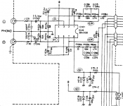
The ones I've circled in red i know to be the DC blocking caps which I'll be doing as film. (I'm not wiring linking them) The ones in blue are the ones I'm not certain about whether they are worth changing or not. I use the tone controls so if they are worth it, I'll do it. The function switch is already PP film so doesn't need doing. At present most of these parts are either fine gold or KZ already, but from what i've read (ignoring ESR) bipolar and film caps have far less distortion vs polar caps.
I've been doing some reading and have decided to try and remove all of the polarised capacitors from the signal path and replace them with either bipolar or film. Rather than doing it like i did with those overly large panasonics, I'll be sticking with 5-7.5mm radial meaning wima MKS and nichicon ES. I'm just looking for the ones that would be worth doing and those that can be left as is.
The ones I've circled in red i know to be the DC blocking caps which I'll be doing as film. (I'm not wiring linking them) The ones in blue are the ones I'm not certain about whether they are worth changing or not. I use the tone controls so if they are worth it, I'll do it. The function switch is already PP film so doesn't need doing. At present most of these parts are either fine gold or KZ already, but from what i've read (ignoring ESR) bipolar and film caps have far less distortion vs polar caps.
You'll have to look at each cap and its function to decide. Electroylitics aren't all bad when used correctly and the Panasonic ECA series are pretty good for low level audio circuitry. Available from CPC/Farnell eg,
ECA1HAM4R7X - PANASONIC - CAPACITOR, 4.7UF 50V | CPC
Be interesting to hear what you think of the different opamps.
ECA1HAM4R7X - PANASONIC - CAPACITOR, 4.7UF 50V | CPC
Be interesting to hear what you think of the different opamps.
Just realised i've been a dimwit and forgotten to attach the schematic with the red/blue circles. As said all these parts are already quite new and are either nichicon FG / KZ or panasonic FM / FC (tone control)
BTW, just tried the TL072 and I couldn't really hear any difference between it and the OPA2134 that i just took out. (might get called cloth eared for that)
BTW, just tried the TL072 and I couldn't really hear any difference between it and the OPA2134 that i just took out. (might get called cloth eared for that)
Attachments

Last edited:
Put TL2072 in and i certainly heard a difference, much improved over the 072, borderline the best I've heard. I'll need to put the OPA back in to double check.
The two caps around the opamp are in the audio path.
The other two appear to connect the "ground" of the outputs sockets to "ground" somewhere else. It's not that unusual to see things like that in commercial gear and there will be reasons for it such as maintaing a low impedance at AC when there are lengths of wiring involved. So in a way they are audio relevant and worth replacing with good quality new caps. Depending how much of a "problem" they are overcoming with the grounds they could be some of the most important in the amp 🙂
Not at all... trust your ears and instincts.
The other two appear to connect the "ground" of the outputs sockets to "ground" somewhere else. It's not that unusual to see things like that in commercial gear and there will be reasons for it such as maintaing a low impedance at AC when there are lengths of wiring involved. So in a way they are audio relevant and worth replacing with good quality new caps. Depending how much of a "problem" they are overcoming with the grounds they could be some of the most important in the amp 🙂
BTW, just tried the TL072 and I couldn't really hear any difference between it and the OPA2134 that i just took out. (might get called cloth eared for that)
Not at all... trust your ears and instincts.
A bit more listening has shown that the TL072 is quite noisy compared with everything else i have. The 2072 is just a hair better than the 2134. (even though the specs would suggest otherwise)
Are C122a/b (100uF 10V) in the amp section worth swapping out for bipolar? (as I already have some Muse ES in my parts tin)
Are C122a/b (100uF 10V) in the amp section worth swapping out for bipolar? (as I already have some Muse ES in my parts tin)
Are C122a/b (100uF 10V) in the amp section worth swapping out for bipolar? (as I already have some Muse ES in my parts tin)
You'll only know by trying. They are in a "critical" location as they are in the feedback return for that amplifier stage so whatever is used needs to be good quality and physically small to minimise stray noise pickup as that would then be injected into the input stage. So no long wires !
As to the opamps, well I guess compromise has to come into it. If the noise is noticeable and objectionable at normal level (you have to have the inputs terminated to evaluate, don't leave them floating and open) then it comes down to what you prefer, overall sonics or lower noise. A bipolar opamp such as the 4562 will give the lowest noise at the impedances involved in the phono stage yet sonically you prefer the FET types. There's no easy answer on that.
Well I've stuck in the bipolars and it still sounds the same to me. I imagine that if there is a difference its too small to be appreciable. I'll have to wait on the PET DC blocking caps.

Well I've stuck in the bipolars and it still sounds the same to me. I imagine that if there is a difference its too small to be appreciable. I'll have to wait on the PET DC blocking caps.
Again you have to trust your ears.
I think more often than not the improvements claimed for many passive parts are just the expectation of the user. I know many won't agree on that but I have never had issue with normal good quality commercial parts.
Is NJM2043 unity gain stable?
I just got some NJM2043 from local shop, and thinking of using them as line-level buffer/preamp (expect for vintage musical sound of 1980s). Previously I thought that it's unity gain stable until found this post.
This opamp seems not popular and limited data available. On the datasheet and there is no mention about "stable for gains greater 20dB".
Datasheet NJM2403
Any one know the source/reference for the figure "20dB" above?
Is NJM2043 unit gain stable?
Thanks in advance.
PS: I have no access to oscilloscope.
The NJM2043 is a bipolar opamp (stable for gains greater 20dB)
I just got some NJM2043 from local shop, and thinking of using them as line-level buffer/preamp (expect for vintage musical sound of 1980s). Previously I thought that it's unity gain stable until found this post.
This opamp seems not popular and limited data available. On the datasheet and there is no mention about "stable for gains greater 20dB".
Datasheet NJM2403
Any one know the source/reference for the figure "20dB" above?
Is NJM2043 unit gain stable?
Thanks in advance.
PS: I have no access to oscilloscope.
This RIAA feed back circuit requires a unity gain stable op-amp since the ultimate gain at high frequencies is ~unity. The data sheet open loop gain graph is a straight line down to 0dB so I think, yes, it is unity gain stable.
The circuit shown in post #2 has some obvious errors as it shows the inputs shorted together.
OBTW, please don't use Photobucket!!! It just makes photos unavailable unless you care to sign up for their service. The DIYA site carries photos just fine without help and the constraints are no problem.
Last edited:
This RIAA feed back circuit requires a unity gain stable op-amp since the ultimate gain at high frequencies is ~unity. The data sheet open loop gain graph is a straight line down to 0dB so I think, yes, it is unity gain stable.
The circuit shown in post #2 has some obvious errors as it shows the inputs shorted together.
OBTW, please don't use Photobucket!!! It just makes photos unavailable unless you care to sign up for their service. The DIYA site carries photos just fine without help and the constraints are no problem.
Thanks Steve for your response.
I apologize not having read the datasheet carefully. There is a small note under a table:
" ( note1 ) Closed loop gain should be more than 20dB at use. "
Though it isn't explicitly mentioned as other ones e.g. NJM4562 , it could be safe to have gain > x10.
> There is a small note under a table:
Under the entry for Maximum Output Swing.
The input swing is less than the output swing. At unity gain, this limits the swing. At higher gain the swing is output-limited.
It appears that a gain of 1.2 would get the input in the clear while the output slams. Performance may be a hair better at higher gain.
I agree this is Unity Gain Stable, and nobody cares about output swing where the RIAA curve has come down to near unity (above 50KHz).
> There is a small note under a table:
Under the entry for Maximum Output Swing.
The input swing is less than the output swing. At unity gain, this limits the swing. At higher gain the swing is output-limited.
It appears that a gain of 1.2 would get the input in the clear while the output slams. Performance may be a hair better at higher gain.
I agree this is Unity Gain Stable, and nobody cares about output swing where the RIAA curve has come down to near unity (above 50KHz).
Thank you for your response. I am learning and try understanding the spec in datasheet.
Though I honestly admit I don't fully understand what you post, it made me re-read the spec again and catch this:
ABSOLUTE MAXIMUM RATINGS
Input Voltage Vic ± 15 V ( note )
( note ) For supply voltage less than ±15V. the absolute maximum input voltage is equal to the supply voltage.
■ ELECTRICAL CHARACTERISTICS
( note1 ) Closed loop gain should be more than 20dB at use.
1) Does it also imply unity gain stable (but performance will best at >20dB as PPR mentioned)?
2) Will this opamp suitable for making buffer (gain x1) or low gain preamp ( x3) ?
Last edited:
The circuit shown in post #2 has some obvious errors as it shows the inputs shorted together.
Not correct 🙂
That´s Luxman´s way of drawing schematics. Look at the rest. If 2 lines are crossing, they´re not connected. If connected, there´s a "dot" where they cross 🙂
> There is a small note under a table:
Under the entry for Maximum Output Swing.
The input swing is less than the output swing. At unity gain, this limits the swing. At higher gain the swing is output-limited.
It appears that a gain of 1.2 would get the input in the clear while the output slams. Performance may be a hair better at higher gain.
I agree this is Unity Gain Stable, and nobody cares about output swing where the RIAA curve has come down to near unity (above 50KHz).
Well done! So that explains the 33 Ohm resistors (33+68)/68 = 1.49. And I notice how they cleverly avoided huge electrolytic caps by returning the feedback to the 68 Ohm resistor only and using a 1 meg resistor for DC feedback. The low value resistors are probably the best choice for noise but I have to wonder about the output loading.
BTW, the actual circuit is probably this:
Attachments
Last edited:
- Status
- Not open for further replies.
- Home
- Source & Line
- Analogue Source
- Luxman Integrated phono stage improvements