How will it affect the speaker performance with such an ohm dip. It can't be any worse than what I'm running now in its draw.
It is more of a guideline than a rule. If this dip were in the bass region then I would be more concerned.
Technically, it can cause distortion or even damage to equipment so I would be remiss if I didn't suggest the change. While I was doing so, I realised that this would mean larger inductors. I am willing and able to adapt this crossover to any minimum impedance that you specify.
Technically, it can cause distortion or even damage to equipment so I would be remiss if I didn't suggest the change. While I was doing so, I realised that this would mean larger inductors. I am willing and able to adapt this crossover to any minimum impedance that you specify.
Is it possible to make so that it doesn't dip below 4 ohms without drastically increasing the sizes? Outside of big changes to resistors or capacitors. Sadly inductors are easily the most expensive stuff to buy.
With regard to the impedance dip. Such a dip wouldn't normally put me off, still it should be noted that the impedance file contains invalid phase data and so cannot be trusted.
Allen, I wrote something else
But it is not the subject 😉... I verified with actual measurements it was worst. ...
I have an other proposition, impedance is above 5.8ohms...
My comment designing passive crossover can take a lot of time.
Attachments
I verified with actual measurements it was worst.
You have this midrange on hand? Your suggestion makes a good starting point. Perhaps Istoc should go with it, and we'll have feed back soon enough.
Would you think it fair to use an iron cored inductor for the woofer?
I had to pull the bottom off the speakers to get the values again. I lost my old notes on the values used. The current crossover are as follows:
Tweeter: 3.6uF .91mH
Midrange: Just one of the high pass and low pass
Woofer: 27.0uF 7.0mH
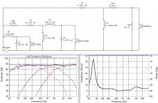
Remember your original crossover, not so bad. See schematics below.
I strongly suggest to test it before ... The sensitivity is 83dB, but you can increase the sensitivity to 86 dB ... Adjustments must be done by listening. Suppress Rms2, Rmp2, Rms = 3.3 and Rts=3.3 Rtp = 15 (the overallimpedance is above 8.6 ohms)
I think I finished

Attachments
You have this midrange on hand? Your suggestion makes a good starting point. Perhaps Istoc should go with it, and we'll have feed back soon enough.
Unfortunately no 😱. If i would have the data, I'll give them 😉
But i have other measurements of mid (seas MCA15, Fountek FR88 EX etc.) in other speaker with 8"+mid+1"tweeter. I can see if things are similar, drivers have similar pistonic range.
BTW this project is an example to read Unfortunately interesting things are in French. If i make an abstract :
1. Choose the drivers
2. Measure the drivers T/S
3. Calculate the volume of the boxes
4. Do a study of the driver placement
5. Design the box ... and make it
6. Make measurements and verify your study about the placement
7. Design the crossover (choose the points etc.) : we are in this stage here 😉 and make the crossover.
8. Listen, make adjustments and measurements.
I saw a similar tutorial on this website and can't find it 😕
The problem a high resistance value of L modifies the T/S parameter of the woofer, changes the behaviour of the speaker in the box, and you loose sensitivity.Would you think it fair to use an iron cored inductor for the woofer?
You doesn't have a lot of choice, a cheap core inductor or an expensive big air inductor. Ferrite core are better than iron core, they make less distortion in the mid.
It appears in your modification of my current crossover values that the midrange is several db quieter than the other two drivers.
Yes because it's a full LR2 crossover. I didn't understand why you have LR4 goals and you do not achieve them. I think LR2 between the woofer and the mid is enough. But between the tweeter and the mid, it is more difficult to say. Only listening tests can say. To make a correct LR4 crossover in the treble, you may need actual measurements. According to my experience, my ears a LR4 gives better result.
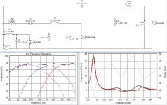
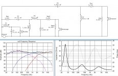
I done a schematic with LR2 at 500Hz and LR4 at 2800Hz see below, min impedance is 5ohms. The second schematic if you keep your original values.
I done a schematic with LR2 at 500Hz and LR4 at 2800Hz see below, min impedance is 5ohms. The second schematic if you keep your original values.
Attachments
I'm sorry to say that I'm not understanding the LR4 and LR2 reference, I'm assuming it's Linkwitz-Reilly.
Allen thanks for working on modified crossovers. Up to 3mH values are awesome. I can get air cores up to about 3.6mH before i have to move to iron core.
Allen thanks for working on modified crossovers. Up to 3mH values are awesome. I can get air cores up to about 3.6mH before i have to move to iron core.
Last edited:
Second order Linkwitz-Riley and fourth order. Each order represents a fall of 6dB per octave from the crossover point, and the LR respresents the rounding of the 'knee'.
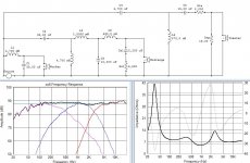
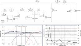
This plot is the same as the last one except I've targeted the individual driver goals rather than the total goal. I wasn't intending to aim at a total response until I got into the impedance dip, and I noticed you were concerned about the midrange level (which is reasonable, but complicated). I've just shown where the tweaks for this are.
This plot is the same as the last one except I've targeted the individual driver goals rather than the total goal. I wasn't intending to aim at a total response until I got into the impedance dip, and I noticed you were concerned about the midrange level (which is reasonable, but complicated). I've just shown where the tweaks for this are.
Attachments
So would you say this revision is the best we are looking at for overall response and such without measurement?
I can see no reason why you shouldn't start with a little baffle adjstment. Looking back I notice that Jerome also incorporated this in his last design. The impedance is reasonable and I think you should go ahead and build.
Do you have a method of creating joints?
Do you have a method of creating joints?
Connections between the components. 😉
Initially you may want some crocodile clips or clip leads, or maybe a breadboard. Eventually you will want to solder.
Initially you may want some crocodile clips or clip leads, or maybe a breadboard. Eventually you will want to solder.
I can see no reason why you shouldn't start with a little baffle adjustment. Looking back I notice that Jerome also incorporated this in his last design. The impedance is reasonable and I think you should go ahead and build.
...
Yes and Istoc keep in mind the baffle is a straight transmission line, the response in the bass is not as flat as a bass reflex. It needs more equalization (baffle step), and damping.
- Status
- Not open for further replies.
- Home
- Loudspeakers
- Multi-Way
- 3-Way Crossover Assistance Request.