This has been a disastorous DIY build. Everything iaw BOM. What a waste of money.
No help from designer at all, just comments like " Must be your choice of components". PCBS are appaulling.
No help from designer at all, just comments like " Must be your choice of components". PCBS are appaulling.
I once had a power amplifier oscillate at 18MHz caused by the CC on the front end BJT LTP, I proved this by replacing the CC with a resistor.
Try connecting a temporary 100nF 50V ceramic cap from the wiper of WR1 to -V.
Try connecting a temporary 100nF 50V ceramic cap from the wiper of WR1 to -V.
Seems odd that both are doing the same thing - stinks of poor design to me.
I'll give it a go and report tomorrow.
I'll give it a go and report tomorrow.
I'm waiting anxiously. I cant see anything wrong with the build. Everything is correct and well built.
Cookbook mentions nothing about capacitors.
Hi Andy,
the cookbook mentions the two caps........
I am so sorry that you had no success with the new PSU....😡
I see only the possibility you build one (or two) channels meanwhile point to point in your B1 case, to compensate for the endless frustration.......
I would give up at this point...

until you get from Zen Mod new stuff..... and when your PTP are running well ........ you nail them on the wall😀😀😀
Attachments
OK missed that one.
Anyway. One of the Pumpkins has recommended 5pF Silver Mica and the requisite R5/R6 = 100K.
Can anyone explain Phase Reversal. One guy suggested that the 20MHz oscillation may be due to Phase Reversal between the PSU and the Pumpkin ????
Anyway. One of the Pumpkins has recommended 5pF Silver Mica and the requisite R5/R6 = 100K.
Can anyone explain Phase Reversal. One guy suggested that the 20MHz oscillation may be due to Phase Reversal between the PSU and the Pumpkin ????
When I built the Pumpkins they oscillated with the 5pf silver mica compensation caps C1 and C2. The oscillation was about what you are describing. I installed some twisted wire and started trimming. If I remember correctly the 5pf cap caused the frequency response to peak at about 300MHz.
BDP
BDP
Last edited:
When I built the Pumpkins they oscillated with the 5pf silver mica compensation caps C1 and C2. The oscillation was about what you are describing. I installed some twisted wire and started trimming. If I remember correctly the 5pf cap caused the frequency response to peak at about 300MHz.
BDP
My stocks of low pF caps are nil. Consequently I'm having to buy nnew values every time.
where did you put the twisted pair (PSU wiring perhaps). What value did you substitute for C1/C2 ?
One of the Pumpkins now has 27K for R5 and R6 with no change to the 5pF caps. The oscillation is the same.
Can anyone suggest a brutal approach to see if this the area of the problem.
(I'm a computer systems engineer - not an audio designer)
I've just tried a bi-filar wound toroid on the PSU wires to see if I can stop the Pumpkin reflecting back into the Shutky - No change.
OK, I'm playing now.
With R4 and R6 at 27K and C1 and C2 at 33pF (because that's all I've got).
Pumpkin oscillates beautifully at 9MHz and almost 8V Pk=Pk amplitude.
With R4 and R6 at 27K and C1 and C2 at 33pF (because that's all I've got).
Pumpkin oscillates beautifully at 9MHz and almost 8V Pk=Pk amplitude.
I need a few suggestions here.
I have a few ideas but not the knowhow how to implement them.
Firstly reduce gain to Less than 1, then it CAN'T oscillate.
Secondly reduce bandwidth to peanuts (say 10kHz), then it CAN'T oscillate.
ONLY once I've got rid of the oscillation can I start to take some meaningful measurements.
ALL the matched components were supplied by ZenMod - that's not to say that either a component failure or a mismatch isn't causing the problem.
ALL components are correctly inserted, and their values checked correct.
Amp (2) has R5 and R6 at 27K and C1 and C2 at 33pF. The only difference now is that Amp (1) (Original vlaues) oscillates at 20MHz and Amp (2) oscillates at 9MHz ????????
Attachments
Last edited:
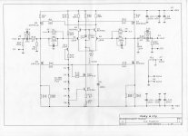
Take C1 and C2 OUT. You have 100k feedback resistors - these things are not doing anything to help stop oscillation.
R2 and R4 should be left at 10k.
You need to drastically reduce the loop gain of this pre amp. I proposed yesterday that you changed WR1 to 500 Ohms. If you do not have a 500 Ohm pot, try inserting a 470 ohm resistor either side of the 47 ohm pot.
R2 and R4 should be left at 10k.
You need to drastically reduce the loop gain of this pre amp. I proposed yesterday that you changed WR1 to 500 Ohms. If you do not have a 500 Ohm pot, try inserting a 470 ohm resistor either side of the 47 ohm pot.
R2 and R4 are 10K
Playing with WR1 is only possible by replacing it.
I'll see what happens with no caps for C1 and C2.
Playing with WR1 is only possible by replacing it.
I'll see what happens with no caps for C1 and C2.
Bottom line is you need to reduce the loop gain until the thing stops oscillating. Once you have this done you can then start optimizing the compensation. But, step one must be to stop the oscillation. Best way to do this is to put the resistors in hat I mentioned.
reduce R2 and R4 to 2K7
put 2K7 between collectors of Q4 and Q3
Shall I work on the amp with 2.7X or 10X gain ?
To save the delicate PCBs I'll try bridging R2 and R4 with 3K9 and soldering a 2K7 as suggested by Alexander.
- Home
- Amplifiers
- Pass Labs
- Pumpkin preamp - ordered by Steen , official making thread