wireHAt
Please, qusp, don't read this!
I plan to drill eight tiny holes so the metal HAt in the LME49720HA is on the same side of the pcb as the buffers and the leads protrude on the side where the 49990s would have been on a rework SE-SE. The pinout is nearly perfect for this but the power is for both opamps. Should I increase the 1uf bypass in value?
I know the resulting noise level, crosstalk, etc. will degrade slightly but I believe so strongly in ceteris paribus (and I have 720s looking for a home 🙂
I promise to also rework one and use 49990's so qusp will still call me buddy.
Hi Guys,
Just a quick update with a new list showing what has shipped and what is going to ship out over the next week.
I'm committed to having everything shipped out before the 23rd with the exception of the power amplifier kits, and I will be sticking to that.
I'm still waiting on the new SE-SE boards to arrive which is holding up any order with an SE-SE PCB in it. They had put the order on hold due to an error in the top silkscreen but failed to tell me about it, so it set that order back a full week and a half. If all goes well, they should be here by the end of this week which means there's nothing holding me back from shipping all the remaining orders. I also have a few days off work in the next two weeks which will allow me to catch up!
On the list, anything in green has been shipped, and the ship date is listed.
Cheers!
Owen
Attachments
Hi Owen,
I am new at this forum. This Headphone amp is exactly what i need to complement my new pre-amp.
Hope i am in time to sign up for a BAL-SE kit and a PSU kit?
I am new at this forum. This Headphone amp is exactly what i need to complement my new pre-amp.
Hope i am in time to sign up for a BAL-SE kit and a PSU kit?
I'm sure Owen will update with available PCBs/parts for the Wire projects as soon as all the orders are out and received.
yeah if you can handle just pcb, for sure he has some, kits as TheShaman says you'll have to wait till after the dust settles on the current GB's

Payment made, Im excited!
Owen, did you ever post the updated BOM you talked about a few pages back after the schematics?
Owen, did you ever post the updated BOM you talked about a few pages back after the schematics?
Hi, yeah i know igor, I saw it just before. the last few days have been absolutely bonkers for work, i must say though that your query is a bit vague and if you look for my posts on the subject you will see quite plainly that i prefer the AKD12P, i'll drop you a line in the next day or so, i gotta go take care of some work first.
Hi Guys,
I've updated the Wiki with all the BOMs and the schematic. They are at the very bottom if you scroll all the way down.
"The Wire" Headphone Amp GB - diyAudio
Regards,
Owen
I've updated the Wiki with all the BOMs and the schematic. They are at the very bottom if you scroll all the way down.
"The Wire" Headphone Amp GB - diyAudio
Regards,
Owen
Keeping the option open
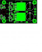
Until the wireHAt is actually working I will not post pix. I have posted an image to show where the eight 1mm holes should be drilled in the TO-99 pattern. It will be more difficult to drill these after components have been added. The holes should not affect construction of the board in any way if using the specified components.
The LME49720HA offers dual opamps so one will handle both buffers. Keep in mind that the leads must be insulated when passing through the pcb to avoid contact with the inner layer. The part is similar to the popular 4910HA but distortion and crosstalk will not be as good as the 49990 and its cost is greater :-( I have a specific reason for wanting two of these for comparison with the BAL-BAL but cannot imagine many others wanting such a frankenwire.
WOw, you guys are going to have to post pics of some of these frankenwires!
Until the wireHAt is actually working I will not post pix. I have posted an image to show where the eight 1mm holes should be drilled in the TO-99 pattern. It will be more difficult to drill these after components have been added. The holes should not affect construction of the board in any way if using the specified components.
The LME49720HA offers dual opamps so one will handle both buffers. Keep in mind that the leads must be insulated when passing through the pcb to avoid contact with the inner layer. The part is similar to the popular 4910HA but distortion and crosstalk will not be as good as the 49990 and its cost is greater :-( I have a specific reason for wanting two of these for comparison with the BAL-BAL but cannot imagine many others wanting such a frankenwire.
Attachments
Running at +/- 17V
Hi OPC (and all other interested!)
Provided I use electrolytic caps with a higher voltage rating, do you think it would be harmful in any way to power the Wire at +/- 17V instead of 15V (or 12V) as recommended (stability, heat, anything else)? For me the only issue might be fitting the larger capacitor on the tight board...
The reason is to simplify power supply efforts (semi-long story) but I'll be using a similar LM317/337 power supply to the one designed by OPC, only it is running at +/- 17V
Thanks for your thoughts in advance!
PS OPC, I'm not yet in green on the PDF, but crossing my fingers for an xmas miracle 🙂
Hi Guys,
The "Build Wiki" is now live for these amplifier boards. It contains pictures for each of the kits along with detailed assembly instructions. It should be the point of reference for anyone building kits.
Please let me know if there are errors or omissions, as I'd like to minimize confusion and have a reliable source of info for everyone with questions when it comes to build time.
The Wiki is here:
"The Wire" Headphone Amp Build Wiki - diyAudio
I still need to get a picture of the SE-SE kit put up, and I should have that up by the end of the evening.
I also need to add some comments about ESD cautions.
Fualcr:
+/- 17V is probably not optimal, but it will work if you need to use it. The official suggested voltage is +/- 12VDC, and +/- 15VDC is also not a problem if you really need the extra headroom.
At +/-17V the LME49990 op amps will run very hot, but they are rated for it, so I don't think it will be an issue. The LM49600 will also be a little warmer, but again, it shouldn't be an issue.
Cheers,
Owen
What are people using for a volume control? I was thinking of an Alps pot or maybe the Joshua Tree Attenuator from Twisted Pear Audio. Any input or suggestions regarding other solutions is greatly appreciated.
Thanks again to opc for all the hard work.
Thanks again to opc for all the hard work.
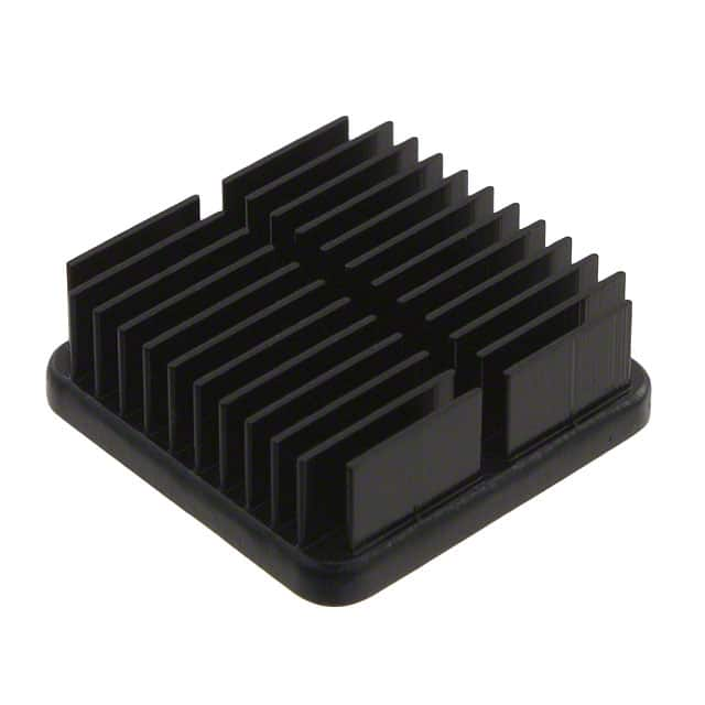
how much copper pour is allocated to each buffer on the pcb? i may need to use alternative heatsinks in my portable, just some small BGA heatsinks like these, which are ~20x20x6.35mm but i need to factor in the rating of the copper area, which may actually be ok depending on how it behaves in my setup.i could maybe even just stick a bit of extra copper foil to the top
An externally hosted image should be here but it was not working when we last tested it.
An externally hosted image should be here but it was not working when we last tested it.
Last edited:
i notice in the guide you recommend rinsing with soapy water, i use noclean flux, so dont always do this, but when i do i use distilled/demineralised water, not so important with plain SMD resistors and ceramic caps, but for the opamps and other ICs i always take this precaution
nice work on the guide though mate!! i think it illustrates well how easily it should come together, i think its great that some of the anti-smd mythology is being combatted
nice work on the guide though mate!! i think it illustrates well how easily it should come together, i think its great that some of the anti-smd mythology is being combatted
- Home
- Amplifiers
- Headphone Systems
- "The Wire" Ultra-High Performance Headphone Amplifier - PCB's