Member
Joined 2009
Paid Member
There are ~0.6V pinch off Jfets to use.😉 My latfets ain't matching also, just picked out off the tube.
What I see in simulations tells me it's not just a bit of voltage drop, it changes the behaviour of the VAS. That's not to say it's bad or wrong, but for me with my limited way of thinking, it's no longer a symmetrical VAS.
Much better than a running away CFP. Irrelevant for your VAS and BJT output stage. Its another amp with same input stage topology. Did you simulate a Sziklai CFP BJT-LAT, or just dropped a JFET in your CCT and simmed? Mismatch the LATs as they really come and it blends nicely enough. If avoidable, then cool. If its a jumpy output CCT on bench, an appreciated band aid.
Member
Joined 2009
Paid Member
I just dropped a JFET in my CCT and simmed. I just happen to have a bunch of BJTs to use up, otherwise I would have bought Lat's just for the change.
If the SSA was driving mosfet like my CFB with EXICON it would also be assymetric by a few volt. because of difference in the N and P channel.
So the few volt accross the JFET does not matter if the total voltage swing is +/-35V...
It will only be noticed by clipping....
By mine BIGBT outputs you actually drive the mosfets and it is interesting how nicely IRF610/9610 Vgs matches not only at threshold level but also across entire Id range, so in my case, SSA is still perfectly symmetrical amp all over. 😉
I use these BIGBT compound outputs (IRF+2SA/2SC) for more than a decade till these days and they never let me down, never noticed even a hint of a local oscillation or any kind of problems and still they can be easily expanded to provide enourmous output currents. The only thing one has to provide is NPN/PNP matching within +/-5% hFE. I guess the answer of its stability lies in BIGBT's symmetrical topology where all artefacts tends to be self canceled within positive-negative side in a balanced way, so it is natural that for a SSA topology BIGBT's are the first option of choice.

Last edited:
Its a very worthy bridge front end from the moment you get to know its traits. Such stuff usually lives on miniscule silicone area, trimmed and thermally homogenous current feedback op amp world. Was a refreshing idea you brought it back to DIY discrete world power amps Andrej. Hats off for that.
Thanks again Salas, bipolar transistors also deserves to be a leading actor in this topology, they need a little more care and understanding than fets, but they also give back a lot. As I already once said, LTP input is not on my menu anymore. 🙂
I just dropped a JFET in my CCT and simmed. I just happen to have a bunch of BJTs to use up, otherwise I would have bought Lat's just for the change.
Hi Gareth, it's your turn now ... TGM5

Member
Joined 2009
Paid Member
Hi Gareth, it's your turn now ... TGM5
Indeed. I'm back from my latest business trip, should be the last this year. Just getting over jet lag. I hope this weekend to start making some progress again.
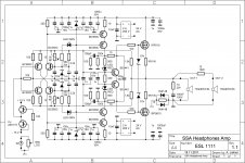
SSA Headphones Amplifier
Hi Dr.H
Here's your mission target.
Hi everyone,
Is there a variation of this amp that can be used to drive headphones?
Thanks
Ryan
Hi Dr.H
Here's your mission target.
Attachments
Active Cat
Hi Lazy Cat,
I must say, you always know how to put a smile on my face with your circuits 🙂
Nice circuit you have there.
You need to change one thing though, your name ! Take away the lazy part and make it Busy or Active Cat 😀
Cheers,
Audiofanatic 😉
Hi Lazy Cat,
I must say, you always know how to put a smile on my face with your circuits 🙂
Nice circuit you have there.
You need to change one thing though, your name ! Take away the lazy part and make it Busy or Active Cat 😀
Cheers,
Audiofanatic 😉
Did-you believe L.C. need to calculate or simulate his schematics like ordinary people ? No, he does it in one gulp, yawning !You need to change one thing though, your name ! Take away the lazy part and make it Busy or Active Cat
LazyCat, you're a very kind contributor! I had in mind to build the big beast for my Apogee Scintilla speakers, but will start with the headphone amp, to learn, to listen, to gain understanding.
Thanks again!
Ryan
Thanks again!
Ryan
Andrej, does your output RC to ground shape out any steady square-wave peak you get, or is it there as a Zobel anti load inductance general?
Lateral MOS + EXICON + V12 Engine - Bugatti
Dr. H, -> You're on the same way as me,
  already
  collecting parts for the Balanced V12 engine for my Scintillas, and as a pudding I'll add to the collection this little marvel Headphone Amp.
Andrej, once again thank You for yours "generous" contribution to the DiyAudio Community and make as available such pleasure for deep music & Soul enjoyments . . . .

 ====---> Lazy
  Cat <---====
LazyCat, you're a very kind contributor! I had in mind to build the big beast for my Apogee Scintilla speakers, but will start with the headphone amp, to learn, to listen, to gain understanding.
Thanks again!
Ryan
Dr. H,
-> You're on the same way as me, already collecting parts for the Balanced V12 engine for my Scintillas, and as a pudding I'll add to the collection this little marvel Headphone Amp. Andrej, once again thank You for yours "generous" contribution to the DiyAudio Community and make as available such pleasure for deep music & Soul enjoyments . . . .
====---> Lazy Cat <---==== Fantastic Smiley 09! please let me know how it goes.
I'll be starting with the headphone amp to better understand the topolpgy etc.
Also should just add that I have little spare time so it's probably going to take a while, but then that's why its called a hobby!
Best
Ryan
PS will you start a seperate build thread for the Balanced V12 engine?
I'll be starting with the headphone amp to better understand the topolpgy etc.
Also should just add that I have little spare time so it's probably going to take a while, but then that's why its called a hobby!
Best
Ryan
PS will you start a seperate build thread for the Balanced V12 engine?
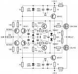
SSA Basic MOS-FET version with J-FET current sources to provide supply current into SSA feedback bridge, serves to compensate collector current thermal drift of the input pair and consequently the bias of the whole amplifier. 😉
This version was inspired by Salas, based on Nico's mos-fet SSA amplifier from early of this thread. 🙂
tempting 🙄
anyone done further work on this one ?
is +/-35V highest possible voltage ?
Attachments
Dr. H,
Andrej, once again thank You for yours "generous" contribution to the DiyAudio Community and make as available such pleasure for deep music & Soul enjoyments . . . .
Fantastic Smiley 09! please let me know how it goes.
I'll be starting with the headphone amp to better understand the topolpgy etc.
Also should just add that I have little spare time so it's probably going to take a while, but then that's why its called a hobby!
Best
Ryan
PS will you start a seperate build thread for the Balanced V12 engine?
I was hoping we could get boards made via GB ..., if not will have to bread board it , point to point .....🙂
Smiley 09 ....any pics yet of the beast ..... ?
Last edited:
tempting 🙄
anyone done further work on this one ?
is +/-35V highest possible voltage ?
I have done a simelar one. The SSA circuit is close to the mirand A1 in performance..
But mosfet sounds less Open as output devices in my opinion... They are not bad at All.
- Status
- Not open for further replies.
- Home
- Amplifiers
- Solid State
- Simple Symetrical Amplifier