A 2channel amplifier using just 5chips.
Beautiful !
My bacon and egg needs more.
Do C3 & C4 need to be as big? The input filter is set to 47ms.
Is there something about the interaction of the 2channels that requires the NFB to be set to 220ms?
Beautiful !
My bacon and egg needs more.
Do C3 & C4 need to be as big? The input filter is set to 47ms.
Is there something about the interaction of the 2channels that requires the NFB to be set to 220ms?
A 2channel amplifier using just 5chips.
Beautiful !
The amp is supposed to work from non-regulated supplies, and the bias needs to be free from ripple.Do C3 & C4 need to be as big? The input filter is set to 47ms.
Is there something about the interaction of the 2channels that requires the NFB to be set to 220ms?
Hi Elvee
Where did you get the LT1056 chips from?
Hard to get hold of here in New Zealand!!!
Great project
Cheers
Where did you get the LT1056 chips from?
Hard to get hold of here in New Zealand!!!
Great project
Cheers
In fact, the LT1056 are for simulation only. They would work in reality, of course, but in practice I use more common types: LF353, LF412, TL072.Hi Elvee
Where did you get the LT1056 chips from?
Hard to get hold of here in New Zealand!!!
Great project
Cheers
Any other good jFET unity-gain stable opamp could do.
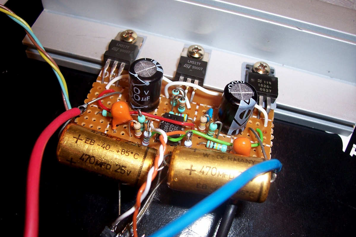
thanks to elvee for the schematic.
just to share the layout that i had come out with.
LM chip to one sided for ease of heat sinking
DC & AC coupled.
single sided using 2 single op amp power bu external dual PSU.
just to share the layout that i had come out with.
LM chip to one sided for ease of heat sinking
DC & AC coupled.
single sided using 2 single op amp power bu external dual PSU.
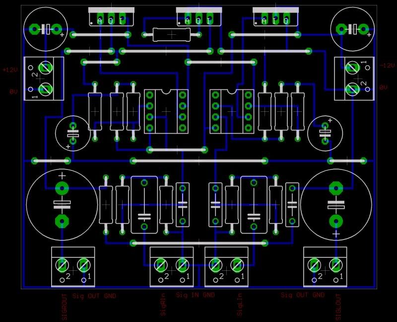
It looks improved and more rational, but there has to be an error (I didn't check everything in detail): C3 and C4 only have one resistor connected to them, there needs to be two.thanks to elvee for the schematic.
just to share the layout that i had come out with.
LM chip to one sided for ease of heat sinking
DC & AC coupled.
single sided using 2 single op amp power bu external dual PSU.
I'll come up with a schematic one of these days, the problem is that the load impedance will need to be 16Ω to benefit from the increased swing, without overloading the current source.Capless output stereo bridge please.
To be able to come back to 8Ω in those conditions would require paralleling regulators. That would be a total of 12 (OK, they are cheap).
thanks to elvee for the schematic.
just to share the layout that i had come out with.
LM chip to one sided for ease of heat sinking
DC & AC coupled.
single sided using 2 single op amp power bu external dual PSU.
The pin order for the LM337 used for the L channel is A-I-O.
hi elvee and magdrop,
thank for spotting the mistakes.
did not realise the LM337 and the connections was wrong for C3 & C4.
had rectified it and here is the re-layout.
thank for spotting the mistakes.
did not realise the LM337 and the connections was wrong for C3 & C4.
had rectified it and here is the re-layout.
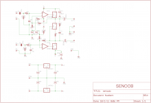
Thanks for the effort.I did a quick and dirty eagle schematic starting from the VSPS pcb files.
Here is how a full bridge version would look like. 12 regulators + 1 quad opamp.
Rather awe-inspiring.
No effort has been made to make a "clever" bridge: the complementary outputs are just that, the complements of the regular outputs.
One could use the complements to not only recreate an opposite phase, but also to measure the actual output voltage and subtract an error signal at the same time.
That's my next assignment.....
Attachments

Sweet!!
I like that circuit!
I will try it once I get some LM317's to work with.
I am thinking of a version that will use some pass transistors to boost the current instead of paralleling the regulator chips.
But I do like it, like it is!!!!!
jer 🙂
P.S. I only have two of them laying around and they are for my ESL bias supply's that I must build next, But keep up the Great Work!!!!!
Last edited:
The power bandwidth extends to ~30KHz. Beyond, the waveform breaks down, probably due to insufficient SR.
The small signal bandwidth (@2Vpp output) is 140KHz.
I was always taught to never wrap a slower amplifier inside the feedback loop of a faster opamp for stability, upon re-reading this post, it occurred to that this is exactly what has been done.
Is it that because the input and output filters limit the frequency response which would make this topology okay?
There are a number of things to consider: first, the regulators operate as followers, and you would probably be astonished by the small signal bandwidth they are able to achieve under those conditions.
And secondly, the amplifier has gain, and the loop is closed via a resistive divider which helps stability by reducing the loop gain.
I tried reading up on opamp theory a bit before replying, but I've yet to come to any conclusions.There are a number of things to consider: first, the regulators operate as followers, and you would probably be astonished by the small signal bandwidth they are able to achieve under those conditions.
And secondly, the amplifier has gain, and the loop is closed via a resistive divider which helps stability by reducing the loop gain.
Looks like 100k / 10k is in the basic non-inverting config of 11x, 22uF rolls gain at DC off to 1x, and 390k serves only to inject a DC offset into the inverting input pin. Use of the last resistor I am not familiar with, and perhaps it also somehow reduces loop gain?
I remember reading in one of these threads that any general audio opamp should work here, but perhaps it would be wise to avoid the faster ones? For example LME49720 with 55MHz GBP still has a whopping 5Mhz Bandwidth after the 1/11 reduction.
I am also curious about your stabilizing network. Does this shared snubber across the current source/sink replace the common RC zobel on each channel? If so, would you recommend additional output inductor//resistor to isolate any capacitive loads?
Use of the last resistor I am not familiar with, and perhaps it also somehow reduces loop gain?
Which resistor?
Using such a fast amplifier would be unreasonable, and would most probably result in oscillation, unless additional compensation components are added.I remember reading in one of these threads that any general audio opamp should work here, but perhaps it would be wise to avoid the faster ones? For example LME49720 with 55MHz GBP still has a whopping 5Mhz Bandwidth after the 1/11 reduction.
Yes, more or less. It is purely informal, and based on trial and errors on the physical circuit.I am also curious about your stabilizing network. Does this shared snubber across the current source/sink replace the common RC zobel on each channel?
The sim doesn't require them to be stable.
YesIf so, would you recommend additional output inductor//resistor to isolate any capacitive loads?
I meant to say the 490k resistor.Which resistor?
I noticed that LF353 has 4Mhz GBP, and perhaps finding a similar spec opamp would be more sane.
The 390K's shift the DC output levels apart.I meant to say the 490k resistor.
.
- Home
- Amplifiers
- Chip Amps
- SE class A regulator-chip-amp madness