triple output stage
if this is a triple output stage where should vbias thermally coupled? in sloans book he said that it should be in the first pre driver transistor stage .does mounting all the pre driver transistors help prevent thermal runaway.or only vbias mounted at final stage is enough to prevent thermal runaway in EF configuration?im confused in this one.
Hi Alex,
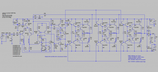
This is how the full amplifier looks.
Thanks.
if this is a triple output stage where should vbias thermally coupled? in sloans book he said that it should be in the first pre driver transistor stage .does mounting all the pre driver transistors help prevent thermal runaway.or only vbias mounted at final stage is enough to prevent thermal runaway in EF configuration?im confused in this one.
If the two stage output (driver and output device) is intended to power a 2ohms speaker then it ain't gonna work.
Try to estimate the peak output current when the 2ohms reactive speaker demands ~three times the current that a 2r0 resistor load would demand.
From there work back through the output and driver stages and try to estimate the driver base current peak that must be supplied by the VAS.
Try to estimate the peak output current when the 2ohms reactive speaker demands ~three times the current that a 2r0 resistor load would demand.
From there work back through the output and driver stages and try to estimate the driver base current peak that must be supplied by the VAS.
Perhaps he is assuming a 4 ohm nominal load with minimum impedance of 2 ohms?If the two stage output (driver and output device) is intended to power a 2ohms speaker then it ain't gonna work.
Try to estimate the peak output current when the 2ohms reactive speaker demands ~three times the current that a 2r0 resistor load would demand.
From there work back through the output and driver stages and try to estimate the driver base current peak that must be supplied by the VAS.
Hi Alex,
This is how the full amplifier looks.
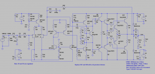
I think the 2200uF NFB capacitor is a total exaggeration, and could certainly be reduced to a value where even film types could be used, like 80uF or so. Don't you think so?
The input cap probably too, to even smaller values.
The schematic shows +-40Vdc and states 200Watts into 2ohms.
If he meant 4ohm capable and 2r0 test loading then I would expect to see that somewhere.
If he meant 4ohm capable and 2r0 test loading then I would expect to see that somewhere.
C8 is silly large.I think the 2200uF NFB capacitor is a total exaggeration, and could certainly be reduced .......Don't you think so?
The input cap probably too, to even smaller values.
C6 is sensible, but near the upper end of what is more normally specified, but still well short of DC coupled.
Last edited:
about vbias
im talking about the correct placement of the vbias so that output transistor will not result in thermal runaway.i know that v bias provides the correct base current for these pre driver stages.does mounting this predrivers on the same heatsink with the output devices prevents thermal runaway?should the predriver mounted separately on the main heatsink(output transistor)?
cheers,
joel
Perhaps he is assuming a 4 ohm nominal load with minimum impedance of 2 ohms?
im talking about the correct placement of the vbias so that output transistor will not result in thermal runaway.i know that v bias provides the correct base current for these pre driver stages.does mounting this predrivers on the same heatsink with the output devices prevents thermal runaway?should the predriver mounted separately on the main heatsink(output transistor)?
cheers,
joel
If the two stage output (driver and output device) is intended to power a 2ohms speaker then it ain't gonna work.
Try to estimate the peak output current when the 2ohms reactive speaker demands ~three times the current that a 2r0 resistor load would demand.
From there work back through the output and driver stages and try to estimate the driver base current peak that must be supplied by the VAS.
Hi Andrew,
Thanks for pointing that out. Would this do ?
Thanks.
Attachments
if this is a triple output stage where should vbias thermally coupled? in sloans book he said that it should be in the first pre driver transistor stage .does mounting all the pre driver transistors help prevent thermal runaway.or only vbias mounted at final stage is enough to prevent thermal runaway in EF configuration?im confused in this one.
Hi Drownranger,
Mounting the Vbe device onto the heat sinks with the predrivers is a place to start.You could also checkout the technique used by the Leach amp. If you have gone through Sloan 196-201, then checkout Cordell 290-313 and Self Chapter 15.
Thanks.
If the two stage output (driver and output device) is intended to power a 2ohms speaker then it ain't gonna work.
Try to estimate the peak output current when the 2ohms reactive speaker demands ~three times the current that a 2r0 resistor load would demand.
From there work back through the output and driver stages and try to estimate the driver base current peak that must be supplied by the VAS.
I have skimmed again through Sloan pages 41 to 42, Burning amplifier, Cordell pages 9,10 and 117-210, Self Chapter 8 and I am still not sure whether a resistive load is not enough.
I think the 2200uF NFB capacitor is a total exaggeration, and could certainly be reduced to a value where even film types could be used, like 80uF or so. Don't you think so?
The input cap probably too, to even smaller values.
Hi Carlmart,
It depends on where you want to cut your low high frequency roll off ........Adjust to your tastes 🙂
Thanks.
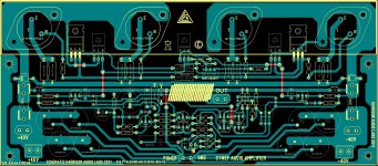
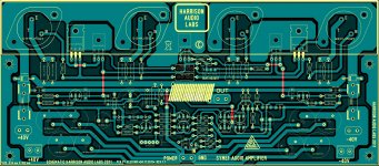
PCB first try.......
....... first PCB for SYMEF rev1.0 😉
Alex.
....... first PCB for SYMEF rev1.0 😉
Alex.
Attachments
Last edited:
thats a good looking board
regarding onboard supply caps
what happens with those thin ground lines when output draws current ?
regarding onboard supply caps
what happens with those thin ground lines when output draws current ?
....... first PCB for SYMEF rev1.0 😉
Alex.
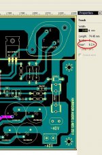
Thanks Alex, that was fast .

I have nothing against the output devices
but they will need 90degr angled alu profile
which will never be a smooth fit to heatsink
heat transfer will be compromised
apart from the other difficulties of drilling, mounting, pads, etc etc
but they will need 90degr angled alu profile
which will never be a smooth fit to heatsink
heat transfer will be compromised
apart from the other difficulties of drilling, mounting, pads, etc etc
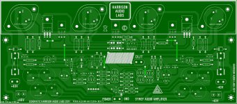
..... and second PCB rev 1.1 for same schematic ......🙂 output transistors can also be connected with wires without problems
Alex.
Alex.
Attachments
Last edited:
I have nothing against the output devices
but they will need 90degr angled alu profile
which will never be a smooth fit to heatsink
heat transfer will be compromised
apart from the other difficulties of drilling, mounting, pads, etc etc
Hi Titinus,
I did checkout a few devices but these ones showed a superior performance 🙂
..... and second PCB rev 1.1 for same schematic ......🙂 output transistors can also be connected with wires without problems
Alex.
Nice Job again Alex. You will love this amplifier 🙂
- Home
- Amplifiers
- Solid State
- SYMEF amplifier