FWIW the first MA-2s (OTLs) that we made were anode-coupled rather than cathode.
Hi Mr.Karsten ( Atmasphere ) !
Just few quick question for you :
It was that yours first MA-2 ( Music Amplifier - 2 ) Anode Coupled OTL Circlotron based model just one laboratory prototype ? , or it was the part of yours standard commercial line of Amps then ?
Is was the presence of full floating B/B`+ Voltage on the Amp both speaker terminals main reason to reject that type of OTL Circlotron Amp concept ?, or was the relative higher generated THD percent from output stage one of the reason ?, and the worse obtained sonics ? or ...... ?
Best Regards !
something like this, in principle ?
hmm, looks almost like a blumlein thing (punctured lines)
Blumlein ? really never heard !, is that name belong to some DIY guy from here ?
All that yours 3 posted schematic have one main mistake ! OPT CT don`t have to be grounded nowhere ! Simply anode coupled Circlotron Amp topology don`t need that .
Right now I`m very busy doing some heavy mechanics repair on some heavy metal machinery , but lately tonight I well attach here one correct schematic for you .
Best Regards !
I would say the first 20?? units employed this technique. There is no particular up or downside to it, you don't have any dangerous voltages on the speaker terminals or anything like that. Ultimately it was easier to wire the MA-2s the same way as the other amplifiers and that is the main reason we stopped.Hi Mr.Karsten ( Atmasphere ) !
Just few quick question for you :
It was that yours first MA-2 ( Music Amplifier - 2 ) Anode Coupled OTL Circlotron based model just one laboratory prototype ? , or it was the part of yours standard commercial line of Amps then ?
Best Regards !
BTW that center tap on the output transformer of tinitus' drawings is similar to what you see in the Wiggins Circlotron sold by Electro Voice.
I would say the first 20?? units employed this technique. There is no particular up or downside to it, you don't have any dangerous voltages on the speaker terminals or anything like that. Ultimately it was easier to wire the MA-2s the same way as the other amplifiers and that is the main reason we stopped.
BTW that center tap on the output transformer of tinitus' drawings is similar to what you see in the Wiggins Circlotron sold by Electro Voice.
Still not understand how you avoid to not have any dangerous voltage on the Amp speaker terminals , since the output AF signal to speaker is than derived direct from both anodes side of OTL Circlotron balanced bridge , and cathodes than remains near to ground potential ?
Original old Wiggins/ Hall/ Koykka Circlotron design is formed from two SE CF unit joined together and OPT CT tied to the ground point is only necessary to get ground reference point for driver circuit and negative bias supply, second way to achieve that is to put two equal resistors from each cathode (or from OPT primary coil both ends ) side to ground , same as you do in yours Atmasphere OTL Circlotron Amps design .
Contrary to that anode coupled Circlotron is formed from two SE AF unit joined together , but still need the same ground reference point , and that is usually derived with two equal resistors from each cathode side .
Think that OPT CT tied to ground well produce short of both B/B`+ and mallfunction of Amp on this type of anode coupled Circlotron Amp .
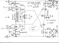
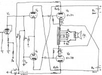
Here is the my proposed schematic for Tinitus
260VDC is economically derived now from Circlotron B/B`+300V supply and is projected to be the stabilized B+ supply for driver and input stage , no need for extra rectifier for that .
Best Regards !
Attachments
you are no doubt a man of experience
valuable details, great
will study
couldn't resist framing your beautifully hand written initials 😀
btw.
the diode at exit of supply (UF5408)
what is it doing ?
and is it important ?
oh, and you asked about Blumlein
would most likely have been on top of things here today
http://www.alanturing.net/turing_archive/pages/blumlein/index.html
Attachments

Hi Tinitus !
This two ultrafast UF5408 diode on the each end of the B/B`+ PSU filter have function to eliminate significant back EMF forces generated from OPT under heavy inductive load operation or heavy AMP clipping or accidentally disconected load(speaker)under full power output condition, its old trick taken from SS power AMP design and have main function to indirect protect the output devices ( here power tubes) .
BTW I made Unintentionally mistake on the posted schematic since I was thinking on EL84 power tubes triode strapped not the present EL34 tubes , so the real RK self bias resistors value are 33o ohm for upper tube and 270 ohm for lower tube, 7W ceramic wirewound type , both CK value remain the same ,only working DC voltage is little higher 220uF/ 63 VDC now .
Thanks for the Blumlein very interesting article !
Still not understand how you avoid to not have any dangerous voltage on the Amp speaker terminals , since the output AF signal to speaker is than derived direct from both anodes side of OTL Circlotron balanced bridge , and cathodes than remains near to ground potential ?
Here is the my proposed schematic for Tinitus
260VDC is economically derived now from Circlotron B/B`+300V supply and is projected to be the stabilized B+ supply for driver and input stage , no need for extra rectifier for that .
Best Regards !
Simple- we simply reference the + side of each floating supply to ground with a 600 ohm resistor, like we do in all the other amps. This put the bias voltage on the grids at a much greater minus value, that of the original bias voltage plus the value of the B+ power supply voltage. That created the need for 600V coupling caps but that was no problem.
In the case of the tinitus amp project, the transformer could be set up in a similar fashion, and could be done as an autoformer. One of the properties of a Circlotron is that the output of the circuit can be set to any voltage potential, regardless of which element of the amplifying devices is driving the output, if you are will to jump through the hoops 🙂
In the case of the tinitus amp project, the transformer could be set up in a similar fashion, and could be done as an autoformer.
One of the properties of a Circlotron is that the output of the circuit can be set to any voltage potential, regardless of which element of the amplifying devices is driving the output, if you are will to jump through the hoops 🙂
speaking of transformer(OP)
please help me understand its function here
I'm confused
output terminal are supposed to be paralelled, 0-0, 6-6, etc
is it different with this amp, not using the CT ?
😕
atmasphere, I understand it like you suggest to make further use of the special balanced transformer design ?
I also had a thought that there might be more in this
keeps spinning in my head I may be missing something there
Attachments
speaking of transformer(OP)
please help me understand its function here
I'm confused
output terminal are supposed to be paralelled, 0-0, 6-6, etc
is it different with this amp, not using the CT ?
😕
ah, ok

Attachments
Hi Tinitus !
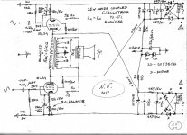
Here is my second concept schematic for Circlotron Amp with same EL34 output tubes ,pseudotriode connected and with same modest 25 W of output power .
Until now we have two basic topology , Anode coupled Circlotron output power stage with 1,6K balanced output transformer, and this my second attached schematic , Cathode coupled Circlotron with your balanced 1,6 K OPT , but Autoformer conected .
Each of this two concept have some advantage and some drawbacks for sure .
Must say that Atmasphere is 100% right for autoformer based output stage sonic superiority performance over the standard transformer coupled to load (speaker ) sonic performance ! ( OTL Circlotron is even better !!! ) .
Third schematic and concept cod be from Atmasphere proposed schematic with Anode coupled Circlotron output power stage,with grounded Circlotron anodes, autoformer coupled to load(speaker ),and superimposed bias supply .
BTW I`m 1000% sure that Mr.Karsten ( Atmasphere ) is the most experienced man on the world for this Circlotron Amp concept !
Best Regards !
Attachments
interesting
tho I'm a bit worried having the output going through cathode resistor (?)
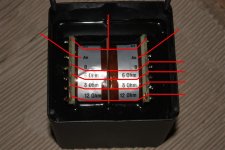
autoformer
does this mean you couple it like in drawing ?
if so, I wonder if there would be a way to also use midpoint from 'primary' ( crossed to grid leak resitors, or something ) ?
tho I'm a bit worried having the output going through cathode resistor (?)
autoformer
does this mean you couple it like in drawing ?
if so, I wonder if there would be a way to also use midpoint from 'primary' ( crossed to grid leak resitors, or something ) ?
Attachments
Tinitus is Nothing to worried about at all !
Fixed bias Circlotron power Amp It`s allredy approved so many times , even in OTL Circlotron power Amp`s topology .
Main AC (music) signal component pass trough both EL34 RK parallel Ck elkos .
Yes it is Correct your drawing for autoformer internal connection !
Autoformer both OO points goes tied to main ground star point , this autoformer middle tap ground point have only function to achieve ground reference point for driver circuit ,and nothing else .
Must admit that I not try to connect G1/G1` grids leak resistors in that way , just think that well be wrong way for Amps sonics quality , but if some small experiments proof opposite results ,than who knows.... ?
That circuit uses a self-bias method. If you were to use fixed bias (requiring a bias supply), you could eliminate the large cathode resistance.interesting
tho I'm a bit worried having the output going through cathode resistor (?)
I like it 
yeah, another member tought me how to properly connect bias pots with neg fixed bias
at least in theory
well, power trafos with double secondaries seems harder to find than expected
but I'm in no hurry
I need to consider all voltages very carefully
can't afford more mistakes
yeah, another member tought me how to properly connect bias pots with neg fixed bias
at least in theory
well, power trafos with double secondaries seems harder to find than expected
but I'm in no hurry
I need to consider all voltages very carefully
can't afford more mistakes
That circuit uses a self-bias method. If you were to use fixed bias (requiring a bias supply), you could eliminate the large cathode resistance.
From the same B- bias supply source could be supplied CCS device in the differencial driver stage tail to . 🙂
thinking about something like this, using autoformer phase splitter
being a design with floating supply, I guess its important to keep good ground reference elsewhere (?)
what do you think about it ?
being a design with floating supply, I guess its important to keep good ground reference elsewhere (?)
what do you think about it ?
Attachments
Wrong Way Man !!!
Autoformer or Transformer for that (inter)stage mean to many concentrated iron & cooper wire on the single unit place , with taking in acount of all negative sonics issue of that(auto) transformer sonics nature regadless to quality of that unit or its price ,it`s good way to do that tube Amp with (auto)transformer phase splitter only for non music or speech tube Amp , but not for the real Music tube Amplifier , to play some sweet music .
BTW I allways have fun when I see that way of tube Amps designs , with transformers implemented in early Amps stages , just remind me on the designs from the era of early 30`.
Best Regards !
- Status
- Not open for further replies.
- Home
- Amplifiers
- Tubes / Valves
- Circlotron questions