This is my latest power board design for LME498xx plug-in amplifier. The board is designed for four-par power device. They can be ThermalTrak or 3-lead TO-264. Pre-driver is included for output triple configuration.
The driver stage can be TO-220 transistor or ThermalTrak. The later is chosen for tight thermal tracking. The schematic is shown here for reference.
The driver stage can be TO-220 transistor or ThermalTrak. The later is chosen for tight thermal tracking. The schematic is shown here for reference.
Attachments
Before I execute systematic test. I briefly test the first assembled unit. No pre-driver is employed in this unit. Four NJL3281D/1302D pairs are used. The driver is MJE15030/15031. LME49811 is assembled in the driver board.
Four TT diodes together with a 500R trim pot are used to generate bias. The power supply is +/- 40 V no load (330VA transformer). The initial result is very promising.
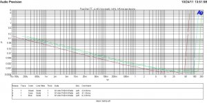
THD vs power for 1kHz and 20 kHz for 8.3, 4.1 and 2.8 Ohms are illustrated in the figure.
Four TT diodes together with a 500R trim pot are used to generate bias. The power supply is +/- 40 V no load (330VA transformer). The initial result is very promising.
THD vs power for 1kHz and 20 kHz for 8.3, 4.1 and 2.8 Ohms are illustrated in the figure.
Attachments

Great stuff Panson. i thought everyone had forgotten about these little drivers.
I am doing a similar 4 diode bias, on bread board so far, but mixing 2 thermal track and 3 standard parts in the same output array (5 pairs). Saves on realestate and seems to work but not sure if I will need to do any matching. Look forward more of your magic measurements.
I am doing a similar 4 diode bias, on bread board so far, but mixing 2 thermal track and 3 standard parts in the same output array (5 pairs). Saves on realestate and seems to work but not sure if I will need to do any matching. Look forward more of your magic measurements.
Great stuff Panson. i thought everyone had forgotten about these little drivers.
I am doing a similar 4 diode bias, on bread board so far, but mixing 2 thermal track and 3 standard parts in the same output array (5 pairs). Saves on realestate and seems to work but not sure if I will need to do any matching. Look forward more of your magic measurements.
Thank you!
I also wonder why they are not frequently discussed in the forum. They really deserve much more attention. Probably beginners prefer single chip like LM3886 and experienced diyers prefer fully discrete.
A very high performance power amplifier in fully discrete is too much work to me. With the LME driver chips, I can focus on the output stage, bias, thermal, etc.
Which standard pairs do you use? I think MJW3281/1302 and NJL3281/1302 should work seamlessly.
Which standard pairs do you use? I think MJW3281/1302 and NJL3281/1302 should work seamlessly.
Hi Panson,
The MJW have the TO247 case. The NJL and MJL both have TO264. I understand the die for them are the same for all the different cases but....
Also, I have gone for the higher voltage spec 4281/4302 for both the 3 pin and 5 pin transistors although in hindsight it probably was not the wisest choice. NPN and PNP gain does not match/track so well although thermal resistance said to be lower.
The other thing is I think I need to go to a 5 diode bias string with the triple darlington, feel it is slightly under compensated - but am I correct thinking you are happy with just 4 diodes? (sorry, I know the bias to and fro has been interminable)
John
The other thing is I think I need to go to a 5 diode bias string with the triple darlington, feel it is slightly under compensated - but am I correct thinking you are happy with just 4 diodes? (sorry, I know the bias to and fro has been interminable)
John
Hi John,
The bias tracking by four diodes is pretty good in my test unit. It actually provides very slightly overcompensation.
Panson
Hi Panson,
I've been using 15034/15035 for the drivers. The HFE measurements are closer for the N channel vs P channel. Like you I plug in the front end to the current amplification section of the layout. This way I have been able to try lots of variations of different front ends and current amp designs. I went down the regulated front end route with a Salas V1.2 shunt, it helped a bit, but, not much. My current front end is a descrete design made by Paul bySouth. It has lower noise and THD at low power levels than the LME49811. Not to knock the LME, it works quite well.
I've been using 15034/15035 for the drivers. The HFE measurements are closer for the N channel vs P channel. Like you I plug in the front end to the current amplification section of the layout. This way I have been able to try lots of variations of different front ends and current amp designs. I went down the regulated front end route with a Salas V1.2 shunt, it helped a bit, but, not much. My current front end is a descrete design made by Paul bySouth. It has lower noise and THD at low power levels than the LME49811. Not to knock the LME, it works quite well.
Thermal Tracking
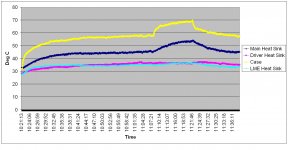
Here are measured data for thermal tracking. One of the Re voltage drop was measured together with main heat sink, driver heat sink, TT case and LME heat sink temperatures. The ambient temperature was about 25 C.
The test unit used four-pair TT where four of the diodes were used for biase/thermal tracking.
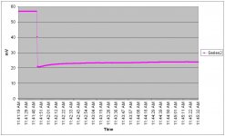
The test unit was in idle mode for an hour. The main heat sink/case temperature moved from 30 C to 45.4 C/57.7 C. The bias tracked the temperature variation pretty well as shown by the Re drop plot.
The test unit then delivered 47 W into 2.8 Ohms for about 40 min. When the signal was removed, the bias was lower than the target point 24 mA/Re (Re = 0.22 | 0.22). It then gradually moved up. Hence, it is a slightly overcompensated tracking system (good to have).
Here are measured data for thermal tracking. One of the Re voltage drop was measured together with main heat sink, driver heat sink, TT case and LME heat sink temperatures. The ambient temperature was about 25 C.
The test unit used four-pair TT where four of the diodes were used for biase/thermal tracking.
The test unit was in idle mode for an hour. The main heat sink/case temperature moved from 30 C to 45.4 C/57.7 C. The bias tracked the temperature variation pretty well as shown by the Re drop plot.
The test unit then delivered 47 W into 2.8 Ohms for about 40 min. When the signal was removed, the bias was lower than the target point 24 mA/Re (Re = 0.22 | 0.22). It then gradually moved up. Hence, it is a slightly overcompensated tracking system (good to have).
Attachments

The other thing is I think I need to go to a 5 diode bias string with the triple darlington, feel it is slightly under compensated - but am I correct thinking you are happy with just 4 diodes? (sorry, I know the bias to and fro has been interminable)
John
Hi John,
Are you using output double or triple? Five diodes may be too high for double unless you want a heavily biased Class AB.
Panson
Hi Panson,
I have just realised you must be using the LME49810.
I am trying to use the 49811. i have the Leach output config but using MJE340/350 + MJE15034/35 + 5 // 4302/4281. For the output transistors I am mixing NJL thermal track with MJL standard for the required number of bias diodes.
On your schematic you show 10 bias diodes in series. I assume you have most diodes shorted out. Does this imply you are using TT diodes in the driver as well as the output?
Could be why I am not so well compensated and maybe I will have to re-think my driver choices.
And great measurements, many thanks
John
Hi Panson,
I have just realised you must be using the LME49810.
I am trying to use the 49811. i have the Leach output config but using MJE340/350 + MJE15034/35 + 5 // 4302/4281. For the output transistors I am mixing NJL thermal track with MJL standard for the required number of bias diodes.
On your schematic you show 10 bias diodes in series. I assume you have most diodes shorted out. Does this imply you are using TT diodes in the driver as well as the output?
Could be why I am not so well compensated and maybe I will have to re-think my driver choices.
And great measurements, many thanks
John
Hi John,
No, I am using 49811. Driver are MJE15030/15031. Pre-drivers are not employed. Only four of the TT diodes are used to generate bias. Other are shorted out.
How do you realized that you have under-compensated bias tracking?
Panson
Panson,
monitor the diode voltages of the unused diodes.
They will give you a much closer correlation with junction temperature.
Cordell, in particular, writes at length of dynamic bias voltage requirements and variations.
4series diodes does not appear to give very good temp. compensation.
5series diodes at a lower current (to be determined) can give better temp. compensation. Read PMA.
Last edited:
How do you realized that you have under-compensated bias tracking?
Panson
Bias current increases slightly with heatsink temperature (heat from a hair dryer).
I am measuring the voltage with a cheap DMM across 0R47 emitter resistor. I am aiming for about 25mA of bias.
If I run at 50mA of bias it very clearly becomes over compensated (bias decreases considerably with increasing temp). I had not realised until now that it was both temperature and current dependent, so I am very pleased with myself for continuing to discover stuff.
If I run 15 to 20mA of bias and 5 diodes in the bias string and a 2K trimpot across the 5th diode I get slight over compensation which is what I have been chasing.
So now for my output transistors I have for NPN 3 x NJL and 2 x MJL and for the PNP I have 2 x NJL and 3 x MJL. Do you see a problem mixing transistors like this? (benefit is lower parts cost and more efficient realestate for the yet to be designed PCB)
And for anyone interested, its spring here, the ski season is over, the snow is melted and today I did a 400km zoom-zoom loop up into the mountains and back on my bike. Exhausted but with a big grin.
I am trying to finish my project for a stereo amplifier with LME49810TB and four pairs thermaltrak transistors on each channel. I am using only LME49810 followed by MJF15030/15031 drivers.The output transistors are NJL0381D and NJL1302D from On Semi.
I have PCB's for LME49810's and for final stages from Panson. I like his work and I can say that the PCB's are very well designed and very well made.
After testing the biasing scheme and making some auditions then I will post some pictures of my amplifier.
I have PCB's for LME49810's and for final stages from Panson. I like his work and I can say that the PCB's are very well designed and very well made.
After testing the biasing scheme and making some auditions then I will post some pictures of my amplifier.
Last edited:
LME49810
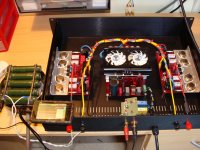
This is a my diy amplifier based on LME49810 high fidelity power amplifier driver. I used a discrete output stage with MJE15032/3 and two pairs MJ15003/4.
The schematic used you can find in driver's PDF. I designed my own layout with separate signal GND of power GND.
The power source is a full-bridge power converter based on ETD49 core.
Pulse modulator control circuit is provided by SG3525 and NCP5181 are power mosfet driver. Without power factor corection.
Soft start is realized by the SG pin 8 capacitor.
Switching power is made with a remote control socket. I transfered the socket's pcb in my enclosure.
The ampl was tested with a dummy load ( five resistors 27 ohms/100W connected in paralel mod).
Unfortunately, my DS203 signal generator can't give a output signal more then 1Vrms.
The sound is great.
Best regards,
Mircea Crisan.
Attachments
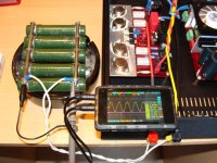
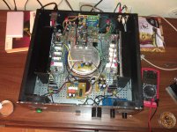
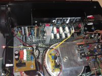
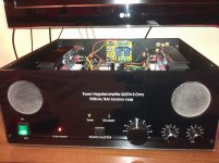
Pictures with my LME49810 amplifier. You can see the wiring which is a big mess but sound is perfect, I do not have any hum or his so I declare myself satisfied. I will rearrange all wires ... in the future. 😀
Attachments

- Status
- Not open for further replies.
- Home
- Amplifiers
- Chip Amps
- My Hi-End/Current LME498xx Amplifier