I need a high-voltage, about 140V power supply. It should be able to provide me with a constant 30mA. Let's call it 50. So nothing too exciting in terms of power. My only demand is for it to be fairly small in terms of size.
What's my best shot? If it's a boost converter, I'd like it premade. If it's now switched - I can't find any small enough transformers rated at 110V, so I'd appreciate a tip there. Otherwise, I can build a voltage multiplier I guess, but that'll grow in size as well, to some extent.
Ideas?
What's my best shot? If it's a boost converter, I'd like it premade. If it's now switched - I can't find any small enough transformers rated at 110V, so I'd appreciate a tip there. Otherwise, I can build a voltage multiplier I guess, but that'll grow in size as well, to some extent.
Ideas?
Mains are 220V. For a DC-DC boost converter I'll be using 12V adapters probably. I don't mind either, really.
30VA, 230:100Vac transformer will give you a 140Vdc 50mAdc continuous supply and run cool.
Why complicate it with switching?
Why complicate it with switching?
Because of the size of the transformer, mostly. I couldn't locate anything small enough at a 100-100Vac. There are pcb-size transformers I can use, but they don't normally come with 100V output. I can do with less than 30VA, I've already accounted for WAY more current than what I need. 10 mA peak will probably be the worst.
The ability to power everything on a single DC adapter is also tempting, but I'm not too concerned either way.
The ability to power everything on a single DC adapter is also tempting, but I'm not too concerned either way.
Nothing under 300VA at these voltages, actually. That's why I was wondering if there's any other sources I can check for items like that, possibly the tube enthusiasts could give me a tip.
Maybe this can help.
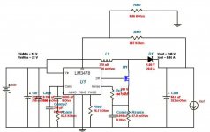
Please check the attached schematic.
It comes from my Nixie Clock, which uses a 180V voltage for light the Nixie tubes.
On the schematic, in the right upper part, you can see a NE555 chip (IC5), a mosfet (Q7) and a transistor (Q8) which serve the scope of elevating the 12V supply voltage to 180V.
The 180V load is about 10mA, so you should play with L1 inductance and 555 frequency to obtain your 30 (50) mA.
Not exactly the most efficient circuit, but I can ensure really small.
Of course you can increase the input voltage up to 18V, or use an higher voltage for the power mosfet (24V?) and a lower voltage (12V) for the NE555 (few more components).
And you should add some sort of filtering at the output, if you want to use it for audio. And, again, some sort of shielding.
I don't have any picture of my clock, but HERE you can see it on the online shop where I bought the PCB.
In the last row of the gallery the third picture from the right shows how small is the voltage elevator stage.
Ciao,
Giovanni
Attachments
Actually the R24 trimmer is there for that; turning it from one side to the other you can change the output voltage from about 100 to 240V...
The idea, however, is to use a single mosfet (Q7), a single inductance (L1), a diode (D1) and a capacitor C4); you can drive the mosfet with whatever you want, a NE555, a CD40106, a PWM voltage regulator...
I would use a MC34063 chip with an external transistor/mosfet, as reported on page 6 on the datasheet.
This way you can save the external regulator transistor (Q8).
Ciao,
Giovanni
I will admit I will learn a lot less by using the simple transformer solution.
It is maybe time I started looking at the various switching solutions to see what is involved.
How well they perform, how they suit linear circuits, how cheap they can be and learn quite a bit more of the electronics than I do now.
It is maybe time I started looking at the various switching solutions to see what is involved.
How well they perform, how they suit linear circuits, how cheap they can be and learn quite a bit more of the electronics than I do now.
croccodillo;2753600 I would use a [URL="http://www.onsemi.com/pub_link/Collateral/MC34063A-D.PDF" said:MC34063[/URL] chip with an external transistor/mosfet, as reported on page 6 on the datasheet.
This way you can save the external regulator transistor (Q8).
This is only workable till up to 40V.
Moreover, please keep in mind, that a boost converter is relatively hard and inefficient for such high voltages ratio.
I'd rather suggest a push-pull or a flyback on mains.
Last edited:
I was also going to suggest a nixie tube supply. There are a few schematics around,and I think I even saw a kit for one..Some Google-fu should find a bunch of stuff.
Alright, I found some not too pretentious nixie power boards that I should be able to tune to 140v. They should do fine, at least as a test.
If anyone spots a low-power 100V-ish transformer, let me know.
If anyone spots a low-power 100V-ish transformer, let me know.
This is only workable till up to 40V.
Not exaclty.
Please refer to page 6 of the datasheet, where you can see the MC34063 driving an esternal transistor.
Imagine to replace the transistor with a Mosfet, power the MC34063 with 12V and drive the mosfet through the internal transistor with such a voltage...
You can go up with the output voltage as much as you need.
Remember that the NE55 I'm actually using for my nixie is rated at 18V maximum...
Moreover, please keep in mind, that a boost converter is relatively hard and inefficient for such high voltages ratio.
I'd rather suggest a push-pull or a flyback on mains.
Absolutely right!
Remember, however, that the original poster asked for small footprint; actually, he can't even fit a small transformer+rectifier in its project (BY THE WAY, what are talking about?): if he can live with a 12V power supply source (maybe an external wall-plug PS) the boost topology is the easiest and smallest on the street, I think.
Considering the power involved (180V * 30mA = 5.4W) one could even use a mobile phone charger to power the circuit...
I developed few switching power suppliers for my job in the past (the biggest one was a quasi-resonant haf-bridge push-pull beast, with 1.5KW of continuous output power at 4.5KV -yes, Kilowatt and Kilovolts-), and would not recommend the construction of a SMPS powered by the mains to a non-expert one, even if we are talking about a 10W unit.
Ciao,
Giovanni
Alright, I found some not too pretentious nixie power boards that I should be able to tune to 140v. They should do fine, at least as a test.
If anyone spots a low-power 100V-ish transformer, let me know.
If you already have a low voltage transformer for the rest of the electronics, consider using a miniature mains transformer in reverse. With its "secondary" fed from the low voltage AC supply and output taken from the "primary" side.
Frank
Yeah, I think we settled on what's gonna do the job here. Simple dc-dc or a very small high-voltage transformer.
Attachments
Great job!
This is exactly what I had in mind, when I suggested the MC34063...
But your solution is way more elegant and recent.
- Status
- Not open for further replies.
- Home
- Amplifiers
- Power Supplies
- 140V miniature power supply