I think Papa meant for this to be able to dial in the harmonic distortion that feels good to the ears rather than to remove distortion to its lowest level...I'll take my responses off the air.
mE
mE
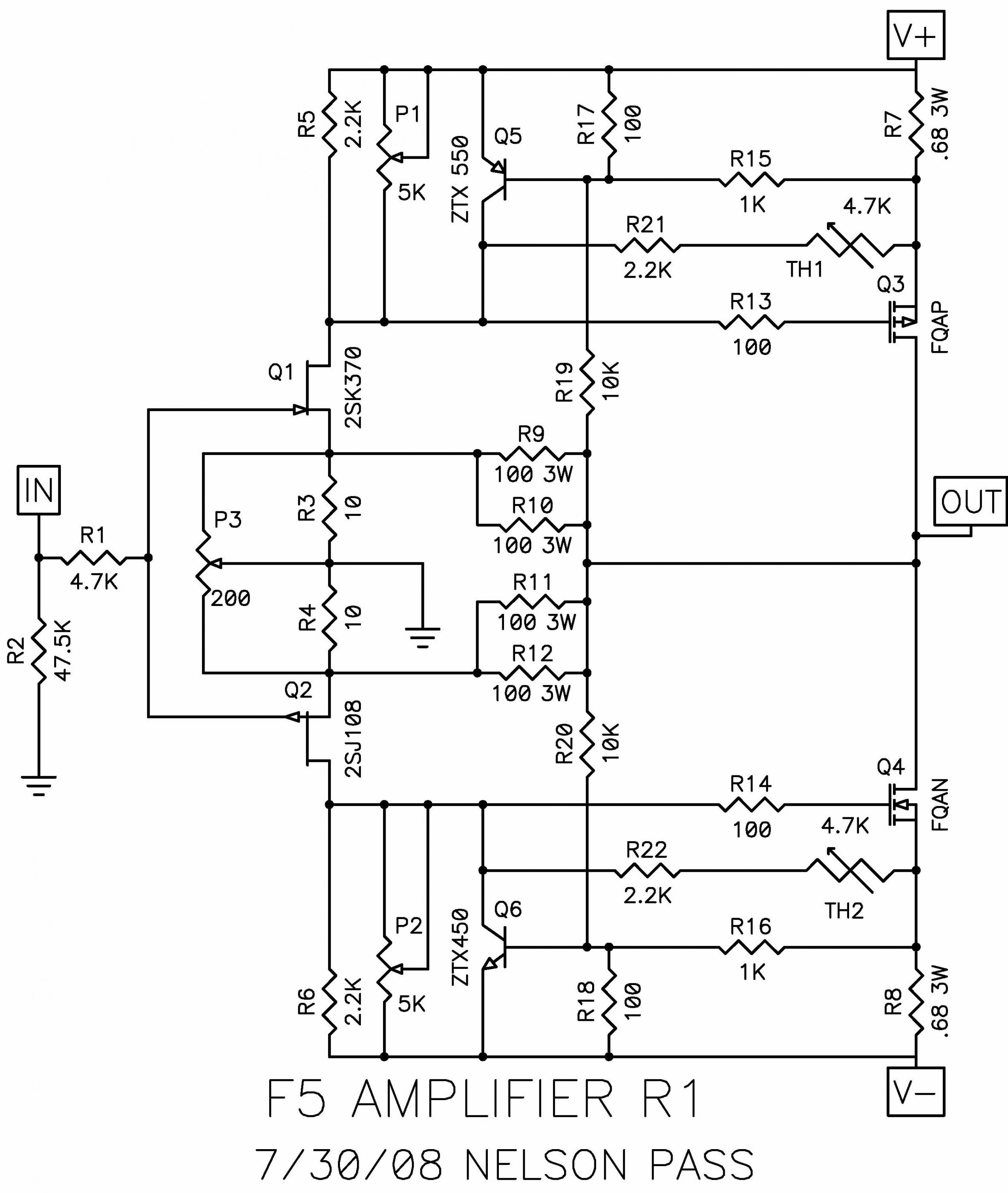
Please give the this schematics and eventually PCBs.I added P3 to my F5’s and could dial in the null very easily. I didn’t like it that way though, so I made second harmonic dominant by 10 dB, its sounded better this way to me though I may go higher. The big change for me was the ability to get the phase of the second harmonic in phase with the test tone. The imaging seams more stable after the modification. It is fun to have a new tool, I find myself testing all my amps to look at the spectrum. Just a note: The BA-3 has much higher distortion and sounds great, so there is more to it than just the numbers.🙂

Thanks

quick F5 question...
I am mounting q3 & q4 off board, and am wondering if r13 & r14 will be too far away from the gate pin ( about 2.5 inches of wire) or do the resistors need to be closer to the gate pin to avoid para. oscill....
Thanks
Sean
I am mounting q3 & q4 off board, and am wondering if r13 & r14 will be too far away from the gate pin ( about 2.5 inches of wire) or do the resistors need to be closer to the gate pin to avoid para. oscill....
Thanks
Sean
Power supply
Hello,
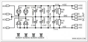
I have received the rectifier/capacitor borads (x2) as per attached images. However they donot implement the Resistors between the caps as per original F5 design.
Should I use as is, or is it better to modify the circuit to add the 4 0.47R resistors between the capacitors and the 2.2k resistor right after teh rectifier as per F5 design?
The 2.2k would not be hard to implement, but the 4x .47R would be a pain given the PCB spacing.
Thanks.
Hello,
I have received the rectifier/capacitor borads (x2) as per attached images. However they donot implement the Resistors between the caps as per original F5 design.
Should I use as is, or is it better to modify the circuit to add the 4 0.47R resistors between the capacitors and the 2.2k resistor right after teh rectifier as per F5 design?
The 2.2k would not be hard to implement, but the 4x .47R would be a pain given the PCB spacing.
Thanks.
Attachments
Hello,
I just noticed another issue - the rectifiers are in a weird configuration with AC to ground. I guess I'll have to use proper recifiers or re-wire.
Thanks
I just noticed another issue - the rectifiers are in a weird configuration with AC to ground. I guess I'll have to use proper recifiers or re-wire.
Thanks
Hello,
I just noticed another issue - the rectifiers are in a weird configuration with AC to ground. I guess I'll have to use proper recifiers or re-wire.
Thanks
Just put the center tap of the transformer to the center/ground. Also I would add the resistors to the bottom of the board they will lower the ripple on the supply.
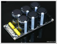
Ok, thanks. Just realized that the electrolytics might be fakes, but rated 80v they should hopefully behave at 18v. I'm planning to use one board oer channel.
I have received the rectifier/capacitor borads (x2) as per attached images. However they donot implement the Resistors between the caps as per original F5 design.
Should I use as is, or is it better to modify the circuit to add the 4 0.47R resistors between the capacitors and the 2.2k resistor right after teh rectifier as per F5 design?
The 2.2k would not be hard to implement, but the 4x .47R would be a pain given the PCB spacing.
The 2.2K in the original design is not critical to placement, (nor value, actually) it's just to discharge the PSU at shutdown. Place that resistor in the pads where the 10K resistor is shown in the attached schematic. Or just leave the 10K in place -- it's a bleeder.
The 4 x .47R are important, and although it might not be the prettiest, you need to use them. Lift the trace between C106 & C108, and also C107 & C109 and use them there.
I just noticed another issue - the rectifiers are in a weird configuration with AC to ground. I guess I'll have to use proper recifiers or re-wire
Are you using a transformer with a center-tap? Or one with dual secondaries? The configuration of your PCB is fine for dual secondaries. Remember, it is a (V+ V-) design, and the positive DC will go to 'ground' on the bottom (negative) half.
Last edited:
Ok, thanks. Just realized that the electrolytics might be fakes, but rated 80v they should hopefully behave at 18v. I'm planning to use one board oer channel.
FWIW, I've seen a couple of "F5" PSU kits from eBay where the capacitors were definitely, no doubt about it, fakes. Fakes in the sense that one was (a) not even a series made by the manufacturer, and (b) no where near the right size for the purported voltage. In the other kit, the caps claimed to be of a real series but were 15 mm too short to be the capacitor they claimed to be on their wrapper.... Anyone's guess what the real current ripple and voltage handling were for those fake capacitors.
As others have pointed out, you really need those 0.47R resistors for filtering. You can look up "pi filter" on the net (where you will see mention of using either resistors or inductors). The 2.2k resistors allow the capacitors to bleed their charge after you power things down. Otherwise, that capacitor bank will remain energized for some time and can give someone a shock. (Made me wonder years later why my Dad always let me be the one to reach into the TV or radio to pull the tubes for testing.)
Dan
Thanks for info.
I'm wondering if the voltage rating positively affects the lifespan of the capacitor if only used at 25% of rated voltage. Otherwise is the ripple current rating the only factor (other than the temp rating?). Given the F5 is class A, power supply caps lifespan is of concern (or should it be?).
I'm wondering if the voltage rating positively affects the lifespan of the capacitor if only used at 25% of rated voltage. Otherwise is the ripple current rating the only factor (other than the temp rating?). Given the F5 is class A, power supply caps lifespan is of concern (or should it be?).
Thanks for info.
I'm wondering if the voltage rating positively affects the lifespan of the capacitor if only used at 25% of rated voltage. Otherwise is the ripple current rating the only factor (other than the temp rating?). Given the F5 is class A, power supply caps lifespan is of concern (or should it be?).
If you have capacitors which are fakes, then you have no idea what you have and you should toss them and get capacitors for which you know the specs.
As to your question, yes running them at lower voltages helps extend the life a little as there's less stress to the dielectric layer. And the closer you approach the rated voltage, the more electrolyte is consumed by self-healing. However, the primary factor in the life of an electrolytic capacitor is the temperature it is operated at. So ripple current (which causes self-heating), and the ambient temperature are the two key factors which will drive the aging of an electrolytic capacitor. And, there's a basic 10 Kelvin rule of "a drop in ambient temperature of 10K doubles the life expectancy" (Arrhenius equation for capacitor life expectancy).
Yes, I'm going to toss the unknown capacitors. Should have been careful and not order risky stuff. Thanks.
Another Hum-question...
Just finished my F5 and I have one little problem. When the amp is idle one channel has a bit of hum. The hum gets much worse if I turn the preamp off and goes away completely if I short the input. The other channel is dead quiet and not affected by turning the preamp off.
Any ideas what this could be?
/U.
PS: Even with the slight humming, the sound is absolutely fantastic! 😀
Keep the bad hum channel connected.
Does the hum reduce when you disconnect the good channel?
But do remember to power down before swapping connectors and allow some time for the caps to substantially discharge. ClassA does this very quickly.
Does the hum reduce when you disconnect the good channel?
But do remember to power down before swapping connectors and allow some time for the caps to substantially discharge. ClassA does this very quickly.
Hi Nesbeth.
Swap the inputs and see if hums goes with it ,if not yep it's in that channel,I know this may sound funny but use your finger to see if you can find some heat or if it reduces the hum at some spots ,it puts you in the ball park,,,got a scope? if yes connect it to the input with a known signal on it and then the output and start backwards it will be found in there some where and I have put parts in incorrectly and sometimes It's good to get another pair of eyes to check your work!!!! If one side is good you have a place to check to, so check one side then the other ,There are other things like ground loops and signal mismatch but check the circuit first,,,,,,,hope this helps you!
Good luck !!!!!!!!!!!!!!!!!
- Home
- Amplifiers
- Pass Labs
- F5 power amplifier