Hi guys,
I rarely use the distortion built into my Hartke amplifier.
Now, I like the amp's clean sound, but the distortion isn't great, being a couple of LEDs in the feedback loop of an op-amp. Goes loud, though, so I'd like to make the rest of it more usable. Currently, I rely on a Boss multifx, which takes longer to set up and play.
Free Schematic Diagrams Hartke GT60 Schematic Diagram - you can download the schematic here.
I can't remember who it was, but I know someone on here has used (with success) transistors in the feedback loop of an op-amp. I'd like to try this, but I'm not entirely sure how such a thing would be wired.
Of course, I'd be willing to try switching other diodes in (I've heard germanium sound different to silicon), but I'm mostly curious about the thing with the transistors.
So, could whoever it was please post up a schematic of some form - it'd be very much appreciated.
Thanks in advance,
Chris
Well I wasn't the guy who posted up but I can tell you some Fulltone pedals use transistors like diodes in a circuit to clip the signal and they sound great. Depending on what transistors you want to use you'll have either a NPN or a PNP. You'll probably want to use two of the same type and wire them in place of the LEDs from emmiter to base only and don't connect the collector.
My experience is that germanium sounds more tube like and much better for Bass guitar.
My experience is that germanium sounds more tube like and much better for Bass guitar.
You can take the LED"s out of the feedback loop and instead put them on the output of the opamp to get a different sound ...... never liked the sound of diodes in the feedback loop , I allways liked them better at the output ......
Cook Your Own Distortion
not sure if its too late, but "shaka bradda" clipping seems to be what is mentioned on this website near the bottom of the page
not sure if its too late, but "shaka bradda" clipping seems to be what is mentioned on this website near the bottom of the page
I added some wires and a connection block to the board so I can switch in different diodes and things. Tried a green LED one way, red LED the other.
Still not the sound I'm after.
So, I put a scope on the output of the Boss multifx I like so much. Turns out it's making a sort of rounded triangle wave, but all the points are moved to the right.
Picture a triangle wave, combined with a sawtooth wave where the leading edge is sloped, the following edge is vertical. Round off the results a little and that's the wave I'm after. I'll post a picture up this evening for clarity.
Methinks that'll be beyond a simple op-amp with a couple of diodes, so will probably revert it back to original.
Chris
is it a bit like the "soft clipped wave" on the website diagram? if so i think that is beyond just clipping, theres also a bit of EQ that comes into getting that shape. mainly boosted treble and cut bass before the distortion, and plenty of mids... i hate it when i see an amp with scooped mids... the midrange is where distortion sounds best.
I have found a schematic of a ''soft clip'' opamp circuit and is using both NPN and PNP pair in the feedback loop..one could be switched out if you want to only clip one half of the wave, apparently that would be more like tube preamp distortion. With both in the feedback loop you get a kind of tube output stage distortion where top and bottom of wave both soft clip. It is a bit messy on the schematic, but I will try to clean up and post it. Not tried yet so ''buyer beware''
Hi guys, apologies for the delay, I've had other things on with college etc.
Anyway, here's a similar wave I found on t'interweb
http://i2.photobucket.com/albums/y41/jolem/Scope%20Traces/BOSS%20FZ-2/Sine_Mode1_Max.jpg
Except all the waves were of the width on mine. I don't think this can be done in the analogue domain so easily (some kind of expander, perhaps?), so I think I'll just stick to using my pedal for everything.
Shanx, I'd be interested to see that - cheers.
Chris
Here is the circuit (not mine, so again just to illustrate). Showing a 2N2804 and 2N2222 in the FB loop and paralleled with a 500 K pot for sensitivity. This in theory would give a logarithmic curved output. Would be an interesting circuit to play around with, as the transfer curve should give a smoother clip.

ah ive seen that shape, i cant remember exactly how to get it but hard clipping, and low cut/hi cut are in order. or, some valve diodes in the opamp feedback loop could work,
Hi Razorrick,ah ive seen that shape, i cant remember exactly how to get it but hard clipping, and low cut/hi cut are in order. or, some valve diodes in the opamp feedback loop could work,
Yes I tried to look back to find where it came originally from, but was unable to. I had just grabbed it to save to my ''notebook'' for possible future reference. It is very basic and like you say maybe interesting to put some filtering in circuit. Haven't tried it yet but figured may be useful FYI to people looking at this thread.
 Cheers
well the filtering in that circuit i posted was 160hz bass cut with 15k treble boost (though 1.5k-3k would probably be better) then the hi cut at the end is 1.5k (though 3k might be better)
While we are on this topic, has anyone DIY built distortion pedals using the transistors in the FB going to the op amp or at the output? I am interested in giving it a go..my pedal board still has a couple of empty spots on it. I built point to point wired board based on a MXR Dist+ that I might base it on. Maybe a switch to go to either diodes or transistors...
never used transistors but im guessing its just going to have a softer clip, as it will clip less at lower levels. i think i might give it a try tomorrow. i'll post how it goes
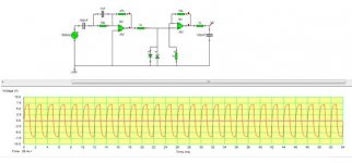
My design, "even softer" soft clipping.
I've been playing with this recently (LTspice .asc file with .txt suffix added for uploading, rename without the .txt extension to load into LTspice). This is the latest I've been playing with in simulation - I've made an actual circuit with only 10 (!) pair of diodes and all the associated resistors being 10k, but the circuit I made does have some unique properties. The distortion doesn't really "sound" much different, except that as you decrease the volume of the input (guitar), the distortion reduces somewhat, but the sound does NOT completely 'clean up' as it does in most other distortion circuits and amps. I designed it to be an "even softer" soft clipping in an effort to let more of the tone through, but I don't quite hear that. I haven't tried any high-pass filter before the distortion stage, but I think that's my next step.
View attachment soft_clipper_1N914.asc.txt
In simulation, +/-6V input (change the Vinitial and Von of V1 to these values) results in pretty much flat clipping with +/- 12V output, but even as low s 0.05V you can plainly see a curved/distorted version of the triangle input on the output.
Cool..I will also post here when I get something going too.never used transistors but im guessing its just going to have a softer clip, as it will clip less at lower levels. i think i might give it a try tomorrow. i'll post how it goes
I've been playing with this recently (LTspice .asc file with .txt suffix added for uploading, rename without the .txt extension to load into LTspice). This is the latest I've been playing with in simulation - I've made an actual circuit with only 10 (!) pair of diodes and all the associated resistors being 10k, but the circuit I made does have some unique properties. The distortion doesn't really "sound" much different, except that as you decrease the volume of the input (guitar), the distortion reduces somewhat, but the sound does NOT completely 'clean up' as it does in most other distortion circuits and amps. I designed it to be an "even softer" soft clipping in an effort to let more of the tone through, but I don't quite hear that. I haven't tried any high-pass filter before the distortion stage, but I think that's my next step.
View attachment 245473
In simulation, +/-6V input (change the Vinitial and Von of V1 to these values) results in pretty much flat clipping with +/- 12V output, but even as low s 0.05V you can plainly see a curved/distorted version of the triangle input on the output.
Hi BenB, I did not see your schematic, as I don't have LTspice. I think you are right about doing some prefiltering on the signal, A hi pass should keep the bottom end from sounding too fuzzy/muddy, if that is a sound that you are going for.
- Status
- Not open for further replies.
- Home
- Live Sound
- Instruments and Amps
- Modifying in-built distortion: transistors in an op-amp feedback loop?