A small introduction:
Back in those days there was the tube, only tube, and amplifier-technology was developing around tube-properties.
But then the transistor was invented. Didn't get so hot, had a longer lifespan and was virtually unbreakeble.
Since there allready was a amplifier-technology, the tube got merely replaced by the transistor.
Tube-amplifiers with transistors. There was no real transistor-amplifier design! Untill now.
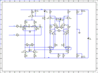
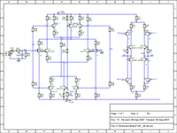
The acompanying circuit shows the schematic of the poweramplifier.
Some feature's;
Completely ballanced.
Inherently stable, no frequency compensating capacitor needed.
Frequency range from DC to 150Meghz.
Shortcircuit proof.
No dynamic load on the powersupply, so no need for low impedance powersupply. I even use a unregulated, transformer rectifier elco, powersuply.
Pure classe A.
As musical as a tube-amplifier but without the coloration.
So rich in detail that the need to turn up the volume is no longer needed.
A discription;
The inputstage is a differential stage converting the input voltage to a differential current.
Loaded by a high impedance ballanced currentmirror. Followed by the outputstage wich is again differential loaded by a high impedance ballanced currentmirror.
The outputstage draws a constant current of about 2Amp. wich is also the peak current deliverable to the loudspeaker, therefore the shortcircuitproof.
Also drawn are two possible inputs, one ballenced filtered, one single-ended input filtered, Dc and to about 90khz.
And it is easy adaptable to different, lower or higher power. Different voltage-powersuply needs a different voltage zener to get the output around the middle.
And the output transistors need heavy cooling.
The whole is my design completely and anyone interrested can build one for his own domestic use.
It is not on the market, I yet need to find a company who´s willing to market it.
I am currently working on a MC-MM phono-stage using the same technology offcourse, and planning on a line-stage with tone-controll as wel as a single-ended to ballanced converter.
Eddy
Back in those days there was the tube, only tube, and amplifier-technology was developing around tube-properties.
But then the transistor was invented. Didn't get so hot, had a longer lifespan and was virtually unbreakeble.
Since there allready was a amplifier-technology, the tube got merely replaced by the transistor.
Tube-amplifiers with transistors. There was no real transistor-amplifier design! Untill now.
The acompanying circuit shows the schematic of the poweramplifier.
Some feature's;
Completely ballanced.
Inherently stable, no frequency compensating capacitor needed.
Frequency range from DC to 150Meghz.
Shortcircuit proof.
No dynamic load on the powersupply, so no need for low impedance powersupply. I even use a unregulated, transformer rectifier elco, powersuply.
Pure classe A.
As musical as a tube-amplifier but without the coloration.
So rich in detail that the need to turn up the volume is no longer needed.
A discription;
The inputstage is a differential stage converting the input voltage to a differential current.
Loaded by a high impedance ballanced currentmirror. Followed by the outputstage wich is again differential loaded by a high impedance ballanced currentmirror.
The outputstage draws a constant current of about 2Amp. wich is also the peak current deliverable to the loudspeaker, therefore the shortcircuitproof.
Also drawn are two possible inputs, one ballenced filtered, one single-ended input filtered, Dc and to about 90khz.
And it is easy adaptable to different, lower or higher power. Different voltage-powersuply needs a different voltage zener to get the output around the middle.
And the output transistors need heavy cooling.
The whole is my design completely and anyone interrested can build one for his own domestic use.
It is not on the market, I yet need to find a company who´s willing to market it.
I am currently working on a MC-MM phono-stage using the same technology offcourse, and planning on a line-stage with tone-controll as wel as a single-ended to ballanced converter.
Eddy
Attachments
nice design, i like it 🙂 i plan to incorporate and try balanced current mirrors in my following amp (that amp i build with many components in very short sockets, so i can easily try out various topologies here and there)
Nice design.
Not efficient though. LTspice suggests 8W RMS into 8 ohm with the PSU pumping out 75W.
Not efficient though. LTspice suggests 8W RMS into 8 ohm with the PSU pumping out 75W.
It looks interesting. Have you done any linearity measurements? It seems you're going by local gain settings in the current mirrors only seeing there's no global feedback as far as I can tell.
I assume you don't actually mean this. There are plenty of SS designs which don't look anything like "valve designs with transistors in". For a start, where would you find complementary polarity valves?EddyF said:There was no real transistor-amplifier design! Untill now.
I assume you don't actually mean this. There are plenty of SS designs which don't look anything like "valve designs with transistors in". For a start, where would you find complementary polarity valves?
With that I mean it's all Op-Amp like. And an Op-Amp is the ultimate meant to be a tube. High impedance input for starters.
I was mostly inspired by M. Hawksford by his description of how the transistor works and from there I started designing, to this and continuing.
I think some people might wish to differ from your view that op-amps and valves are almost the same thing. There is more to life than input impedance. Open-loop gain, transfer characteristics, frequency response are all very different.
Many SS amps look a bit like the innards of a basic op-amp, for quite sensible reasons. However, there are SS designers (such as Nelson Pass) who do things differently, and have done so for quite a while.
Many SS amps look a bit like the innards of a basic op-amp, for quite sensible reasons. However, there are SS designers (such as Nelson Pass) who do things differently, and have done so for quite a while.
This is actually a bridged version of the totem pole circuit used in early TTL logic, then adapted to high voltage amplifiers made by Burleigh Instruments and subsequently published by Horowitz & Hill. Much more evolved, but conceptually operating in a very similar manner. The downside to this technique is horrendous efficiency, so it probably doesn't have any commercial application in an energy conscious world. But I've been wrong before- just ask my wife!
I don't think so: the totem-pole I know is more JLH-like (but there might be earlier versions unknown to me).This is actually a bridged version of the totem pole circuit used in early TTL logic, then adapted to high voltage amplifiers made by Burleigh Instruments and subsequently published by Horowitz & Hill.
This circuit is a bridged SE amplifier.
The important part is the bottom one: it is a V-I converter based on a CFP, and must for that reason have a good linearity.
The top half is merely decorative and just has to provide a sufficient source current to keep the CFP's biased.
The top-down symmetry is pleasing to the eye and does no harm, it can even cancel some of the Early effect, but it isn't essential.
The CFP + lateral symmetry certainly contributes to cancel many even order non-linearities.
Apart from energetic efficiency, I would be concerned by the damping factor: I guess it is pretty low, perhaps even <1.
This is actually a bridged version of the totem pole circuit used in early TTL logic, then adapted to high voltage amplifiers made by Burleigh Instruments and subsequently published by Horowitz & Hill. Much more evolved, but conceptually operating in a very similar manner. The downside to this technique is horrendous efficiency, so it probably doesn't have any commercial application in an energy conscious world. But I've been wrong before- just ask my wife!
Precisely what I wanted to say - you beat me to it. The efficiency doubles from that of class A as it is two bridged class A and the output power quadruples in bridged mode while the heating doubles.
Interesting approach if I might say. Class A at the efficiency of class AB or there about.
Nice Idea
The circuit consists of two SE stages.The efficiency doubles from that of class A as it is two bridged class A and the output power quadruples in bridged mode while the heating doubles.
Interesting approach if I might say. Class A at the efficiency of class AB or there about.
Placing two SE stages side by side or in a bridge configuration doesn't alter their basic efficiencies.
(OK, I have demonstrated the opposite, but that's a special case)
Yes, with Operational Amplifier I mean an Amplifier with differential input, high gain and the outputsignal fed
back to the input to control it's behaviour. Be that with tube's,Fet's or BJT,OA.
As I studied many, many circuitry from exotics like Naim, Lin, Nad, Akai(low feedback), Sansui(error
feedforward) or Mission and many more, to expensive-highly praised as Mark Levinson, Krell, Electro-research,
Audio-research(wich still use the tube for its musicality combined with SS for edge-ines) or Threshold(Stasis)
from mr. Pass(who couragiusly stepped out of line, creative designer as he is with the ZEN-projects, proving my
point exactly, I think it's save to say that 99.999 percent of all equipment, outside the tubeworld, is OA.
Save a 1000th percent for circuitry I haven't seen yet or the one mentioned by Conrad Hofman above, Hiraga with
his unconventional MC-Amp, ZEN and Marshall Leach's MC-Amp.
Like mr.Pass tried in his NS10 preamp, a transistor should conduct a vast amount of current that varies with the
processing of the signal. One of my goals.
As for effiency, Hifi-lovers get a warm heart when their amp runs hot, see Krell.
But since this amp poses no dynamic load to the powersupply, a SMPS is easy to use.
Or a switching SMPS, more like Yamaha has done and Carver, low signal low voltage, higher signal higher voltage
That would be a challenge. Only the zener should maybe replaced by a NPN transistor with it's base earthed,
haven't tried that yet.
And for PA, those are designed to run continous at max power with forced cooling.
Another goal was no change in current. The current is constant, only changing from the left side to the right,
the difference going trough the speaker and canceling out any nonlinearity.
The damping-factor, DF, was about 3 in my first attempt, see acompanying circuit. It sounds as solid as a tube,
very musical but with the output variing with the impedance of the speaker, also like a tube-amp.
And I strugled to improve on this, until I tought up the ballanced current mirror.
Now, with this amp, it varies with the quality of the transistors used.
I use high quality Toshiba's and have a DF of 80. With the transistors mentioned it should be 20 or 30, wich to
me, is acceptable.
Eddy
Attachments
one nice advantage of resistive loading of a transistor, additionally, probably known by you; is low thermal distortion of the gain device.
this is used that i know for instance in the tek 454 oscilloscope vertical amp;
4 resistive loaded cascode stages, t-coil and series capacitance peaked, heavy biassed,
open-loop, and flat from 0 to 150Mhz iirc.
this is used that i know for instance in the tek 454 oscilloscope vertical amp;
4 resistive loaded cascode stages, t-coil and series capacitance peaked, heavy biassed,
open-loop, and flat from 0 to 150Mhz iirc.
With that I mean it's all Op-Amp like. And an Op-Amp is the ultimate meant to be a tube. High impedance input for starters.
I would think the closest thing to a valve in the wonderful wide world of sand is a J-fet. BTW, J-fets are superb for use in audio electronics.😉
I've learned not to expect anything that requires an explanation
to draw much of a crowd. The few who can decipher such things
tend to have their own pet designs. Its not that you are doing
anything wrong. Probably the opposite...
I have no idea whats on with this amp. But don't let sane folks
dissuade you from going places that haven't been over-explored
to the point of becoming a tourist trap...
Think it's a litte like Vladimir's singleendede Jfet circuits, just bridged...circlotron principles springs to mind...
Dissipated/output power ratio
Sorry, I wasnt to attentive.
About the power ratio? I have an amplifier running from 25V, drawing about 2A, 55W, and putting out 20W.
That is a more healthy ratio.
But looking closer, it seems that the ratio get worse with lowering powersupply voltage.
Also I use high quality Japanes transistors with high hfe. So also the quality of the parts used is important but in another way.
But I am stil looking in to cranking up the output power with a lower Supply voltage.
And, not yet in the amplifier, but simulated I replaced the zener with a NPN, grounded base. And that works beautiful.
Eddy
Could you explain this part a little more? I follow the rest of the description and circuit, but I do not see two possible inputs (besides the + and - of the balanced input pair).Also drawn are two possible inputs, one ballenced filtered, one single-ended input filtered, Dc and to about 90khz.
Also, which transistors did you use? Are they readily available?
Sorry I had two versions to show.
The input+ you can use for single ended input while grounding the input-.
And I use 2SA970/2SC2240 for the small signal transistors, 2SD966/2SB970 for drivers and 2SC5200/2SA1943 for the power transistors.
I am still trying to get more power for a given Powervoltage. When I succeed I wil publish a new circuit.
Eddy
- Status
- Not open for further replies.
- Home
- Amplifiers
- Solid State
- New Amplifier Technology