guys what do you use for snubber?
i use 1n5822 diodes.
i have some on hand wima mks2 0.1uf/100v
are they any good?
We don't usually. Just good rectifiers. You should be OK with your Schottky basically.
Second Reflektor is working perfectly 🙂
As I did not find any IRF9610 I used one SFP9610.
Fine. SFP looks a bit more capacitive, but not alarmingly so. You are building a symmetric right? So the negative must be IRF610 and NPN TO-92 in the CCS. Any pictures yet?
Trimming after it is hot provides very stable 10.00Vout.
What seems strange is that when powered from cold, it takes 10 seconds to reach 10.13Vout and then starts to go down. It takes 10 minutes to stabilize at 10.00Vout.
In all my other regs the voltage only goes up until it stabilizes.
I will now build a second shunt so I can test them in my p2p DCB1.
That should be the NTC action of the LED. This is not analogous to the other regs at all. Has no JFET controlled by Vbe. 1.3% travel looks fine for a dirt cheap LED and resistor Ref and so many silicon junctions in the Wilson. No wide drift safety issues. Negative drift is safe to the load even if it was much more. Imagine if using it for an op-amp on the verge of its max allowed PSUs. Could be even better if the trimmer gets to be a low ppm resistor finally.
REFLEKTOR 1
The second build is also positive as I am using a TX with double windings and double rectifier bridges.
Yesterday I replaced the V1 with the Reflektor shunts in the DCB1 and now I am waiting for everything to settle (I believe solder joints neet to mature and some caps need some time to give their best).
Inittiall impressions are: Very silent operation, very stable + - 10V reached quite fast.
Trebble detail and transient presentation are quite good but I need to wait a while to be able to evaluate properly.
Some pics:
Attachments


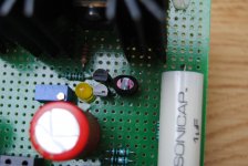
The big cap to the left is an input cap.
Vref cap is a 680uF BGN bypassed by a zobel (025r + 3u3 AudynCap QS)
Output zobel is 2r2 + 1u.
Just to be on the safe side, I used a MCF 120r as base stopper on Q5, so I do not know if it works better without it.
Once I get a true picture of the sonic presentation, I will fine tune.
I will use the 0.2r resistors from Merlin with the 1uF to bypass the Vref cap, and I will reduce the output cap. Maybe it works with a 220nF FT-3.
Last edited:
OK. Nice constructions. Good it works robust without technical problems from get go for a beta circuit.
Yes.... Robust operation, very easy to trim Vout, settles on desired output almost from the start only with minimal deviations (6 seconds to reach 10.13V and 10.00V after 7 minutes).
Output offset on DCB1 changes only 0.1mV from cold start untill it settles on the final values.
After running all night and listening to radio for 4 hours in the morning, I started critical listening in the afternoon and my first impressions are quite positive.
Extended and clean trebble, powerfull rendition of transients, good presence in the mids (particularly in wood instruments) and fully controled bass.
Also very quiet, presenting lower hiss than V1.
It is a keeper. A really good improvement over the "souped up" V1 I was using.
I particularly like the low parts count, low value output cap, ease of implementation, low cost and robust operation.
The only difficulty is related with matching the transistors in the Wilson Mirror. I only got two matched pairs in 40 pieces of BC560C.
Monday I plan to start modding it... I will start by the output zobel... Can I short the 2r2 ?
I've heard Phillips transistors are much better matched. I heard they discontinued the BC5x0, but have better ones now anyways. I haven't looked into it much though.
- keantoken
- keantoken
Monday I plan to start modding it... I will start by the output zobel... Can I short the 2r2 ?
No, you can't short the 2R2, but you can see with 0.22uF Teflon instead the Zobel 1uF cap if its still stable in your application. That will extend it in frequency even more if it will remain stable. Teflon can be used for Vref large cap bypass also for the subjective thing. Nice report so far. 2N4403 as shown in the published beta REFLEKTOR CCTs is a good solution for up to 30V out also. Very cheap, very low noise. A match around 10 units hfe difference is very good for Q1,Q2 no need be absolute.
Sorry if it is a stupid question but is there an equivalent reflektor schema using NPN transistor instead of PNP ?
Sorry if it is a stupid question but is there an equivalent reflektor schema using NPN transistor instead of PNP ?
No, I haven't prepared one, but you can mirror the mirror. Not joking.
No, you can't short the 2R2, but you can see with 0.22uF Teflon instead the Zobel 1uF cap if its still stable in your application. That will extend it in frequency even more if it will remain stable. Teflon can be used for Vref large cap bypass also for the subjective thing. Nice report so far. 2N4403 as shown in the published beta REFLEKTOR CCTs is a good solution for up to 30V out also. Very cheap, very low noise. A match around 10 units hfe difference is very good for Q1,Q2 no need be absolute.
So matching 680hfe with 690 hfe is ok ?
What changes would be needed to build a 37Vout Reflektor ?
SMD reg
For low power usage positive and negative 5V, <40-50mA can I use smd parts?
Could you recommend D2PAK (TO-263) mosfets which would fit (e.g. IRF610s) ?
Thanks!
For low power usage positive and negative 5V, <40-50mA can I use smd parts?
Could you recommend D2PAK (TO-263) mosfets which would fit (e.g. IRF610s) ?
Thanks!
So matching 680hfe with 690 hfe is ok ?
What changes would be needed to build a 37Vout Reflektor ?
Its nice to match, but nothing tolerance related can throw it out of function. Just to compromise best error correction a bit. 5-10% hfe match for Q1,Q2,Q3 will be plenty save perfectionism. 10 in your scale is about 1.5%. Vbe to be near maybe better when already having high hfe transistors like you use. But remember, the Wilson will work fine with medium hfe transistors too.
With your 560s and 37V I don't see a problem for Q3 Vceo or dissipation so don't change something. Just use 10K trimmer for R5. Watch Vin max not to kill J1. J1 will see ~ Vin-5V.
For low power usage positive and negative 5V, <40-50mA can I use smd parts?
Could you recommend D2PAK (TO-263) mosfets which would fit (e.g. IRF610s) ?
Thanks!
You may try, but no expertize to give, never had to make such. Look for TO-263 types near the Ciss, Crss, and gfs of the originals.
IRF(9)610S is the D2PAK version of the IRF(9)610. Same characteristics, but different thermal dissipation capacity. So it should fit for low currents.
It is stable with 0.047uF instead of 1uF in the output Zobel.
Sonically responds to any change done in the output zobel cap.
I am experimenting with RELCAP Polystyrene+Tin Foil after using a 220n FT-3
I will post my subjective opinion later..... very good for now 🙂
Sonically responds to any change done in the output zobel cap.
I am experimenting with RELCAP Polystyrene+Tin Foil after using a 220n FT-3
I will post my subjective opinion later..... very good for now 🙂
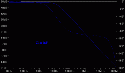
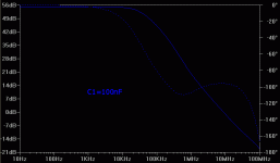
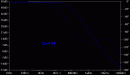
By decreasing C1, extends the open loop gain, remains tame at zero gain point, but turns the phase more in hi-band. That should be quite audible. To know what value keeps it practically stable for enough different load reactions it will take a few different builds for other audio circuits. 1uF is a conservative value. If say 0.1uF will prove universal enough, it lowers bulk and cost. 0.1uF can also be used for C3 doing the big polar cap's bypass action, if it will prove subjectively synergistic.
Can you post some graphs so we can visualize the phase turning ?
I would like to see a 1u sim versus a 0.047u, it would really help to access my subjective listening impressions.
I am not sure what an inversion of phase reflects audibly.
With 0.047u sound gained a lot in spatiality, detail and smoothness but I did not listen long enough to detect the drawbacks.
Bypassing C3 will be my next step 🙂
Last edited:
I can, but in a layout with real components, don't expect it to be what you see from the simulator. Physically small capacitors have extra benefits beyond value play here, remember. It just owes to get worse for in band phase and expand OLG in frequency as a general trend. Also to add on total noise. No expected Zo change.
Attachments
- Status
- Not open for further replies.
- Home
- Amplifiers
- Power Supplies
- The simplistic Salas low voltage shunt regulator