I would love a set of his big monoblocks (509 I think they are).
sp
Hi SP,
I could not find the monoblocks with PL509 - but this EAR 861 , PL519 and circuit by Tim de Paravicini.
HIFI4ALL.DK | Køb Salg Bytte | esoteric audio research 861(ear)
We (and I) highly respect the designs from EAR amplifiers - and not to forget - the sound reproduction. I would wish the TVA-1 to play like the EAR 861, but this hobe is surely out of reach (I think).
The price for a secondhand EAR 861 is 3360 Euro. ( New retailprice 6210 Euro)
Regards
Kim
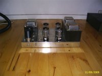
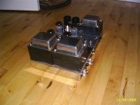
The TVA-1 from Germany just arrived. See attached picture.
Question:
Anybody who knows whether the Tungsol 6550 reissue an/or the TAD 6550C can be used as replacement tubes for the mounted KT88 EH in the TVA-1 as far as 530V is concerned? Don't we say max. 500V on the plates for 6550?
regards
Kim
Question:
Anybody who knows whether the Tungsol 6550 reissue an/or the TAD 6550C can be used as replacement tubes for the mounted KT88 EH in the TVA-1 as far as 530V is concerned? Don't we say max. 500V on the plates for 6550?
regards
Kim
Attachments
i have some company information from michaelson austin
i own a tva1
m100
tvpx 1
groet Rob
from holland
i own a tva1
m100
tvpx 1
groet Rob
from holland
michaelson austin
Herewith I send you some information about the tva 1. I am a collector of Michaelson & Austin.
Herewith I send you some information about the tva 1. I am a collector of Michaelson & Austin.
hi,
any information from michaelson & austin would be highly appreciated!
Regards
kim


Herewith I send you some information about the tva 1. I am a collector of Michaelson & Austin.
Hi Rob,
Thank you for some beautiful pictures. I have never seen the M100 neither the TVPX 1.
Did you attach any paper documentation at this message? - if you did ! - I have not received anything by mail.
I will try to copy the TVA-1 circuit, just to check if it is possible to achieve or come close to the original M&A sound. The TVA-1 sounds just nice on AR3a!
The best regards
Kim
Herewith I send you some information about the tva 1. I am a collector of Michaelson & Austin.
The TVA-1 "clone" idea to be found on:
Michaelson and Austin
Have you made any changes on your TVA-1 ( except the speakerterminals)?
Regards
Kim
Hi
Here is (I think) a schematic from a service manual.
Regards, Torben
Hi Torben,
Some friends in Denmark would like to see the circuit supposed to be the original from TVA-1.
If you don't mind, I will send the circuit to my tubefriends ( I thought: the drawing is already visible here)?
Thanks to Rob for the 1977 advertisements!
Regards
Kim
Hi
I do not mind.
I do not think there is any such thing as only one authentic TVA-1 schematic - I think there were made various changes during production.
Regards
Torben
I do not mind.
I do not think there is any such thing as only one authentic TVA-1 schematic - I think there were made various changes during production.
Regards
Torben
Thanks! Yes - you might have a point there! - I have checked some details in the TVA-1 amplifier of mine, and everything seems to correspond with your drawing.
Regards
Kim
Regards
Kim
Kim (or somebody else)
Earlier in this thread I promised to find the data for the original thermistor in the power supply. Unexpectedly I did not get the opportunity to look at my brothers TVA-1 during christmas holidays and it will be a while before I can do it. Can somebody else do it?
Regards, Torben
Earlier in this thread I promised to find the data for the original thermistor in the power supply. Unexpectedly I did not get the opportunity to look at my brothers TVA-1 during christmas holidays and it will be a while before I can do it. Can somebody else do it?
Regards, Torben
Torben,
I have checked my TVA-1. The thermistor has been changed , and replaced with two glass-resistors of 22R (11R). Simple but not good enough.
It is difficult or impossible to find the original thermistor.
I have one suggestion:
If any of the TVA-1 owners can messure the DC voltage across the thermistor, and important! - Use the same voltage-meter and messure the time in seconds before the high voltage has reached its maximum. My friend Claus has an idea to a simple in-line circuit which is capable to replace the thermistor.
He need the time in seconds , and the voltage across the thermistor to calculate the circuit.
Rgds
Kim
He need the time in seconds , and the voltage across the thermistor to calculate the circuit.
Rgds
Kim
Replacement of the TVA-1 thermistor.
The circuit for a 35 second delay of 520Vdc for TVA-1 and other tubeamplifiers attached.
I will try to explain the circuit function now, but the engineer CK will explain the circuit later (better) on the DIY site called:
www.fundamentalaudio.com
1. The idea is to connect the 520Vdc on both sides of the R1 which is 30R and not 40R (showed in the spice circuit).
2. When the 520V is connected the R2, 1M raises the voltage of C1 (4700u) and the fet starts to open.
3. The 10V zener raises the potential on the gate and keeps it open.
4. The loss over R1 is approx. 6-7volt when the fet leads the total voltage of 520Vdc, and it is possible to use one resistor(1K5) and a light emitting diode parallel with R1 to show when the fet leads the voltage.
5. R1 needs to be appox 3 Watt - a 10-20watt aluminum resistor could be used.
6. Look at the red kurve which indicates the power wattage on the fet. The chosen fet( 800 -1000V) may have different on limits (gate), and C1 can be adjusted to the wanted delay time. Because of the short time (10sec. approx) the total voltage is applied to the fet, the heat from the fet is limited.
7. The R-load is the amplifier(psu) ( not needed)!
The engineer advises to use : Bridge - then capasitor - then delay circuit followed by the large capasitor on the TVA-1.
Rgds.
Kim
Look at the voltage load-lines.
Attachments
Hi, anybody can help on the Power supply transformer for the michaelson & Austin TVA-1 as I plan to build one from the schematic drawing. What is the current rating on the 0-100V and 190-0-190v ? Will 500mA and 800mA respectively is sufficient ?
Depending on the cathode resistor, which could vary from 47R to 100R you could calculate the transformer like this.
Assume that you want to draw 50mA from each valve, and the resistor is the known from the TVA-1 schematic , you get: 47 Ohm x 0,050A = 2,35V ...you can messure 2,35V across the 47 Ohm resistor.
If you want to draw 70mA per valve and use a 100 Ohm resistor ( the KT88 gets more hot ) you get: 100 Ohm x 0,070 mA = 7 V across the 100 Ohm resistor.
You got four valves running at 70mA, and approx. 20mA for the two ECC83 and the two ECC81 all together (might be a little higher), thats 280mA + 20mA = 300mA .....500mA is sufficiant. Forget the last words and keep the 500mA transformer
Last edited:
Thank you very much. Your information definately very very useful for me as I try to build it TVA-1 crone from scratch. I try to secure the custom power supply transformer as well as the output transformer from manufacturer in China.
The output transformer with the secondary winding as 0-4-8ohms and 0-16 ohms. It has 2 sets of windings. I wonder whether each set should work out with 70 w output, if so means 0-4-8ohms output 70w and 0-16ohms output 70w. this case, it may turn out to be 140w? Does it calculate this way?
I understand, in order to have good sound, one should work out more power on the output transformer and so I asked for 80w output instead.
Any advise, please. Thanks.
weak 50-60Hz hum from the TVA-1
Anyone who know the original ground wiring for the TVA-1 made by Michaelson and Austin?
Some soldering work inside the TVA-1 has been done....weak hum detected. How does the original wiring look like?
Anyone who know the original ground wiring for the TVA-1 made by Michaelson and Austin?
Some soldering work inside the TVA-1 has been done....weak hum detected. How does the original wiring look like?
- Home
- Amplifiers
- Tubes / Valves
- Michaelson & Austin TVA-1 info