I have run this in simulation every way I can think of. The only other resistor that could cause this is R12. Do both channels do the same thing?
Steve -- I have a slightly different take on this because of the oscillation. I think that needs to go away before progress can be made but why its there is a mystery to me.
lgreen -- I'm confused by this:
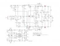
There is no need for any additional resistors or caps when checking the VGS except possibly for C2. I've attached a marked-up version of Steve's post 251 schematic. The X's show where to break electrical connections which you have done. Also remove D11 and D12 which I have circled. Short the input of the VGS to ground as shown by red line.
I think you said you added C22 so remove that capacitor and put in a jumper or just simply jumper over the leads of C22. Check the continuity from a spot on the main ground buss of the PCB to the end of R10 (right on the lead of the resistor) connected to ground; same for C2 if you can get to an exposed lead; and same for R2. You should have zero ohms for each measurement. A good spot to use as the ground point would be the solder pad on the top of the board where the center tap of your transformer is connected.
Measure directly from the other lead (away from ground) of R10 directly to the lead of R11 that is connected to R10. You're measuring right on the lead itself so that you also include the solder joint in the diagnostic. If that's zero then measure from the same end of R11 to the collectors of Q4 and Q6. You should read 20K for both of those measurements.
lgreen -- I'm confused by this:
-this is present with the 1K and .1 uF cap on the input; with no RC on the input; with C2 = 5pF or C2 = 1500 pF.
There is no need for any additional resistors or caps when checking the VGS except possibly for C2. I've attached a marked-up version of Steve's post 251 schematic. The X's show where to break electrical connections which you have done. Also remove D11 and D12 which I have circled. Short the input of the VGS to ground as shown by red line.
I think you said you added C22 so remove that capacitor and put in a jumper or just simply jumper over the leads of C22. Check the continuity from a spot on the main ground buss of the PCB to the end of R10 (right on the lead of the resistor) connected to ground; same for C2 if you can get to an exposed lead; and same for R2. You should have zero ohms for each measurement. A good spot to use as the ground point would be the solder pad on the top of the board where the center tap of your transformer is connected.
Measure directly from the other lead (away from ground) of R10 directly to the lead of R11 that is connected to R10. You're measuring right on the lead itself so that you also include the solder joint in the diagnostic. If that's zero then measure from the same end of R11 to the collectors of Q4 and Q6. You should read 20K for both of those measurements.
Attachments
Hi Phil,
I appreciate any help I can get. A couple of points; It is not necessary to remove diodes D11 and D12, if they are installed correctly. They were included so the VGS supply would come up as fast as the output supply and avoid the start up time constant generated by R23/C19 and R24/C20 in the regulated supply. Once the regulated supply exceeds the voltage on the outputs, the diodes are reversed biased and out of circuit. They also insure that voltage falls at the same rate when the circuit is powered off.
When you say C2, you mean C22, as you said earlier.
lgreen,
If C2 is still in circuit, make sure it is 60V or greater rated. A leaking cap could cause this problem also.
If both channels have the same problem, it is unlikely you have a defective component. That does not rule out an incorrect value in both channels.
thanks
Thanks guys.
Steve-
- I have been holding off on connecting the output transistors to the 2nd board to try and solve these issues first in case I need to operate on board #2. I will assemble it this weekend as we are not making progress and perhaps it will work better or give me some insight into the issues with #1.
- When putting in and removing C2, the caps I have been using are rated at over 100V. Also the cap rating doesn't really matter much since I am observing the same response as the supply comes up from 5v to 20, 30, 40 etc... Unless of course I broke a cap.
PH104-
- I tried without any caps at all. Only added on in series with the input because I had time and a cap, figured I'd give it a try. I even tried a cap to ground. But yes, this should work with just the function gen. on the input.
- I am able to try it with D101 and D102 removed- but remember that the 50v supply is disconnected for checking the VGS. So these should not be conducting.
-I can jumper over the leads of C22 (small one in FB loop) and check it in this condition. It is a 160V 220 uF cap.
-I can make those other measurements.
originally posted by Steve Dunlap
I appreciate any help I can get.
Steve -- I hope that I am helping here and not confusing things. Tell me to butt out if I'm not being helpful.
Steve and lgreen -- I agree with your comments about D11 and D12 but you both also qualified your statements. I'm trying to reduce variables so I'm suggesting that they be left out until its time to test both stages together. That's also why I suggested getting C22 out of the circuit. The 220uF/160V cap is great but let's get it out of there for now.
Sorry about the C2. When I said:
I meant to say C1, the 220pF filter cap at the input..... same for C2 if you can get to an exposed lead;....
To be sure I'm on the right page here:
C1 is the input filter cap,
C2 is the freq compensation cap,
C22 is the DC blocking cap between R10 and ground,
and neither C2 nor C22 are shown on schematic but have provisions on the board.
lgreen -- great on measurements. You don't need to short the input for the continuity measurements. If those measurements check out, then short the input and apply power to the VGS and see how it looks. Then, even if it is does have some small oscillation and offset, attach your sig generator and apply some AC to the input to see if the signal gain is ok. Maybe use 1 kHz at something between 100 - 500 mV on your scope and then, ignoring oscillations and offset, see if you get gain of 21 at the output, i.e., at the junction of R11, Q4 and Q6. I would do this at first without C2 to eliminate Steve's concern about a leaking cap.
If you need to add capacitance there, you can take two pieces of insulated solid wire, like 20 - 24 gauge, and put a fairly tight twist on them. For this, the insulation material doesn't matter. Maybe use about 18" of twisted pair at first. Solder the wires at one end of the twisted pair to the holes for C2 and make sure the wires at the other end shorted out. This will give you some capacitance and then you can reduce it by shortening the twisted pair. You can see what I mean in the pic in my post #151. That's 20 gauge wire there.
PH104 said:
To be sure I'm on the right page here:
C1 is the input filter cap,
C2 is the freq compensation cap,
C22 is the DC blocking cap between R10 and ground,
and neither C2 nor C22 are shown on schematic but have provisions on the board.
Ok, I will use these and I think have been using these in the prior posts; although we have not brought up C1 before.
I will look at the gain, thanks for telling me its supposed to be 21.
lgreen --
You've been consistent. I'm not sure I was so I listed those caps to be sure.
I thought of C1 when you mentioned that 50 kHz oscillation. It's something simple to check and can be a problem if not there.
good luck
You've been consistent. I'm not sure I was
so I listed those caps to be sure. I thought of C1 when you mentioned that 50 kHz oscillation. It's something simple to check and can be a problem if not there.
good luck
Steve -- I hope that I am helping here and not confusing things. Tell me to butt out if I'm not being helpful.
You are being helpful. Thanks.
Yikes!
ouchie! I connected the other channel; the main DC voltages go out of kilter when the variac gets up to about 20 VAC. I get more - than + by about 5 volts and DC offset starts at 5 volts and goes up to 10 or more!
I have not had much time to debug this and am wondering if it will ever be done!
ouchie! I connected the other channel; the main DC voltages go out of kilter when the variac gets up to about 20 VAC. I get more - than + by about 5 volts and DC offset starts at 5 volts and goes up to 10 or more!
I have not had much time to debug this and am wondering if it will ever be done!

Aikido preamp
Has anybody tried Aikido preamp with Krill output stage?
Also what is the output impedance of 50W Krill output stage?
I have build Aikido preamp driving quasi-complementary output stage from Nishiki hybrid, also without any NFB and didn´t like the sound at all. Sound was too soft, not enough bass (not deep or tight) and not much detail either. My LM3875 sounded better.
So is the Krill output stage so much better than ordinary EF power buffer?
Thanks.
Since there is no feedback around the output stage the output impedance will depend on a number of factors such as the number of output pairs and the value of the emitter resistors.
Is the sound better? That depends on who you ask. A number of people made up their minds without ever hearing it.
Hi Steve
I hope everything is OK with you. Last time I got a PM from you was when you got out of the hospital.
Cheers
S
I hope everything is OK with you. Last time I got a PM from you was when you got out of the hospital.
Cheers
S
Since there is no feedback around the output stage the output impedance will depend on a number of factors such as the number of output pairs and the value of the emitter resistors.
Is the sound better? That depends on who you ask. A number of people made up their minds without ever hearing it.
If I will make the Krill output stage with double output pairs of 2SC5200 and 2SA1943, each pair will have 0.1R emitter resistors what output impedance would it have?
And about the sound...can this output stage have same authority in the bass frequencies as some amplifier with GNFB with same power and number of output devices?
Last edited:
Hi Steve - it's good to see you here!!! Do you mind if I give you a call about a couple of things???
Was there ever closure on the issue of the output stage switching or not??
_-_-
PS. has it really been more than 2 years since that discussion was heated??
_-_-
PS. has it really been more than 2 years since that discussion was heated??
Hi Steve
I hope everything is OK with you. Last time I got a PM from you was when you got out of the hospital.
Cheers
S
I am doing mostly OK. I had renal failure a bout 3 months ago. That put me in the hospital for a while.
If I will make the Krill output stage with double output pairs of 2SC5200 and 2SA1943, each pair will have 0.1R emitter resistors what output impedance would it have?
And about the sound...can this output stage have same authority in the bass frequencies as some amplifier with GNFB with same power and number of output devices?
The output impedance with the values you listed will be 0.1 ohm.
Here is one opinion on the sound.
http://www.parttimeprojects.com/audio/diy/Krill.php
- Home
- Amplifiers
- Solid State
- Krill construction thread - 100W version