Another quick test you can do is block off the lower chamber with some MDF attached with some Bostik. This will reduce the volume and automatically increase the Fb by a few Hz closer to 35Hz.
Make sure that the holes in the braces are greater than the Sd of the driver.
Wasn't there another thread on this issue with the ZRT.
Make sure that the holes in the braces are greater than the Sd of the driver.
Wasn't there another thread on this issue with the ZRT.
Ah i see. Thank you for the deep insight, it is much appreciated. I shall look into Troel's comments regarding this wooferA test tone of 30Hz with a speaker tuned (Fb) to 30Hz is going to have very little driver excursion which is the nature of a vented design, but the port should be working. See the excursion graph with about 10W input.
Having used the 18W8531 on several designs, 38 litres is too large and the Fb is too low. Have a look at Troel's designs and comments on the 18W8531 driver. Also have a look at his article on vent tuning where port length is usually 0.7 x calculated to achieve the target Fb.
For a test, try a port that's tuned to 40Hz to see if it makes a significant difference.
I've found 28 litres or smaller vented with this driver works the best and Fb > 35Hz for personal taste.
Try running the woofer without the crossover but add a 1mH inductor in series. This will flatten the response to 1.5k after which it will roll off smoothly. Even though it will not give BSC, it will give an indication of the raw woofer's performance in the box.
Hmm, i think the holes are big enough. The cut out is 6.5", so the area is much larger than the 150 cm^2 SD of the driver.Another quick test you can do is block off the lower chamber with some MDF attached with some Bostik. This will reduce the volume and automatically increase the Fb by a few Hz closer to 35Hz.
Make sure that the holes in the braces are greater than the Sd of the driver.
Wasn't there another thread on this issue with the ZRT.
Yea, i went through the other ZRT thread. It seemed like the guy had some problems with the port - not much output at 30Hz. He said he took out the bracing and that settled everything.. but i'm not too sure if the removed bracing added more cabinet resonance that he preferred and thought it was more quality bass or simply boomy resonance.
Heh, i got around to measuring the impedance using your method. Is there anything wrong with my results?We will try to help you again.
This image, taken from, the website : Measuring Loudspeaker Driver Parameters , shows how to make the measurement for impedance. You really don't need the amplifier if your generator has any balls at all.
An externally hosted image should be here but it was not working when we last tested it.
You can download free programs on the web that act as signal generators and use your PC's sound card to generate the test signal. This gets your amp out of the loop, which may be the real cause of the problem. There are also free programs that allow you to read in the data into the PC instead of a voltmeter.

forgot to mention, as per all the suggestions, i have used a rubber gasket to seal the front baffle up 🙂
Yeah something isn't right with that at all. It could be your multimeter. We are talking about the measurement of AC signals, something some multimeter's aren't to hot with, especially at different frequencies.
I'm assuming that you're using the PC as a signal generator, if that's the case I recommend you download ARTA and use the program it comes with called LIMP, this will allow you to measure the impedance with a set-up very similar to what you used above, except the input of the computers sound card replaces the multimeter.
Of course there might be some very good reason and something that's easily fixable with the multimeter method, but considering how easy it is to use something like LIMP I'd just go with that. The help file that LIMP comes with explains exactly how you need to connect things to take measurement too.
Heh, i got around to measuring the impedance using your method. Is there anything wrong with my results?
I think the shape of the curve is correct. Think about it, you are measuring the voltage across the resistor, btw what value?, so the minimum impedance of the woofer at the tuning frequency should yield a local maximum voltage across the resistor. It appears it does right near 30Hz. Either side of this you see lower voltages showing the characteristic higher impedance of a ported system. In other words think of the curve as being upside down if think of it as an impedance curve.
As I said on the PE forum (SDL2112 there) you need to listen to the stereo pair. From there you can fine tune the port length and reduce the volume if you prefer.
Thank you guys! That is really helpful 🙂 I shall explore LIMP!
The resistor measures about 10.5 ohm.
Anyway, i was doing some comparisons with my existing speakers (dynaudios) and i seem to prefer how the dyns sound with respect to drums and electric guitar, like there's more meat to the toms and electric guitar. The Zaph, in comparison, has more thin-sounding drums. The intro of Bon Jovi - Always illustrates my point. With the Zaph, the drum fill at the start doesn't have the same, natural oomph meaty tone as the dyns.
I hear more of the snap and crackle of the snare drum rather than the toms, and when the electric guitar part comes in, it sounds quite shrilly. I'm not sure if this is a result of the reduced BSC, making the mid range more prominent vis-a-vis the mid-bass. It is not likely that this is a <100 hz problem, right?
Heh, i got around to measuring the impedance using your method. Is there anything wrong with my results?
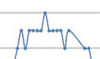
Well, I see some measurement error at the start of the curve. If you abstract the curve it looks like the tuned box frequency is 50 Hz.
I second the idea of downloading ARTA or Praxis and see if you can confirm the results.
If the box is really tuned to 50 Hz, then there is good reason why the bass is anemic.
Man you're quite right, the scale on that graph threw me completely, the twin peaks are obviously there, well one of them is at 50hz the other one looking like it'd be at around 15hz.
I was looking at this bit of the graph.

and was wondering what was going on there. It's perfectly symmetrical too, I wonder why those two blips backwards are there when the impedance should be approach a minimum.
I was looking at this bit of the graph.
and was wondering what was going on there. It's perfectly symmetrical too, I wonder why those two blips backwards are there when the impedance should be approach a minimum.
Attachments
Man you're quite right, the scale on that graph threw me completely, the twin peaks are obviously there, well one of them is at 50hz the other one looking like it'd be at around 15hz.
I was looking at this bit of the graph.
and was wondering what was going on there. It's perfectly symmetrical too, I wonder why those two blips backwards are there when the impedance should be approach a minimum.
No, I am interpreting it as the first peak is around 30 Hz and the second is at about 80 Hz with the valley at 50 Hz.
That first peak is simply measurement error.
Man you're quite right, the scale on that graph threw me completely, the twin peaks are obviously there, well one of them is at 50hz the other one looking like it'd be at around 15hz.
I was looking at this bit of the graph.
and was wondering what was going on there. It's perfectly symmetrical too, I wonder why those two blips backwards are there when the impedance should be approach a minimum.
Likely that is just rounding error, if he took it to the first decimal I'm sure it would smooth out.
No, I am interpreting it as the first peak is around 30 Hz and the second is at about 80 Hz with the valley at 50 Hz.
That first peak is simply measurement error.
NO...
It is a peak but look at the measurement scale. It is the voltage across the resistor thus proportional to the current to the speaker. The speaker impedance is inversely proportional to this current.
Vres=I*R
Vsource=Vspeaker+Vres
Vspeaker=I*Zspeaker=Vsource-Vres
or the speaker impedance
Zspeaker=(Vsource-Vres)/I
Ah, I see what you are saying! Good catch.
Looks 30Hz tuned to me.
If you do 1/ all the voltages, you get the shape of the impedance curve of the woofer.
So, why is there no output?
If you do 1/ all the voltages, you get the shape of the impedance curve of the woofer.
So, why is there no output?
Why would a rounding error like this make something smaller? The plots @ 24 and 36hz have already supposedly been rounded (either up or down) to produce 9 on the voltage scale. The readings taken @ 25 and 35hz should have a higher absolute voltage so should equally round up to 9. For it to round down to 8 volts the voltage taken at 25 and 35hz would have to have been smaller then the voltage taken @ 24 and 36 hz, which is pretty much impossible unless there's an error somewhere.
right this moment I thought I had lost my hearing on the right ear
or that something was broken
right channel only at half of the left, and sounded muffled
when I touched one speaker cable connect to amp, all was ok againg
well, first time this happened to me, and a surprice
makes one think twice about connectors
and all other connections
or that something was broken
right channel only at half of the left, and sounded muffled
when I touched one speaker cable connect to amp, all was ok againg
well, first time this happened to me, and a surprice
makes one think twice about connectors
and all other connections
Why would a rounding error like this make something smaller? The plots @ 24 and 36hz have already supposedly been rounded (either up or down) to produce 9 on the voltage scale. The readings taken @ 25 and 35hz should have a higher absolute voltage so should equally round up to 9. For it to round down to 8 volts the voltage taken at 25 and 35hz would have to have been smaller then the voltage taken @ 24 and 36 hz, which is pretty much impossible unless there's an error somewhere.
I just assume that since he was taking a manual measurement with the multimeter that the display value may not have stabilized and he recorded what he saw at the moment with his own rounding so all his measurements have some error...again this was just to confirm the tuning frequency. I certainly could be wrong though.
Yea you're absolutely right! Some of the values kept hovering between a certain value so i rounded up/down. I guess it's the poor precision of my cheapo multimeter.I just assume that since he was taking a manual measurement with the multimeter that the display value may not have stabilized and he recorded what he saw at the moment with his own rounding so all his measurements have some error...again this was just to confirm the tuning frequency. I certainly could be wrong though.
I will try to use ARTA and measure the impedance again tomorrow. But from the blunt measurements so far, does it seem to suggest that the port tuning is correct?
should i try a higher port tuning of 35 Hz instead of 30 Hz? i'm using the 2" precision port flared ports. According to the vent tuning options, the port needs to be modified to 3" from the default of 4.75". But i see no way to do that if both flared ends need to be used. If i use only one flared end, then the length will be 2.9" with the connecting ring. Will the lack of a flared end on the inside affect anything?
Yes, the tuning frequency does appear correct.
Feel free to try different tuning frequencies...only you can tell you what sounds best...that's why it's called diy😉
And for the last time...you need to listen to the stereo pair😡 I thinks no matter how good a speaker is it would sound sterile and lifeless with one mono speaker.
Feel free to try different tuning frequencies...only you can tell you what sounds best...that's why it's called diy😉
And for the last time...you need to listen to the stereo pair😡 I thinks no matter how good a speaker is it would sound sterile and lifeless with one mono speaker.
Yea you're absolutely right! Some of the values kept hovering between a certain value so i rounded up/down. I guess it's the poor precision of my cheapo multimeter.
I will try to use ARTA and measure the impedance again tomorrow. But from the blunt measurements so far, does it seem to suggest that the port tuning is correct?
should i try a higher port tuning of 35 Hz instead of 30 Hz? i'm using the 2" precision port flared ports. According to the vent tuning options, the port needs to be modified to 3" from the default of 4.75". But i see no way to do that if both flared ends need to be used. If i use only one flared end, then the length will be 2.9" with the connecting ring. Will the lack of a flared end on the inside affect anything?
The flare reduces port noises at high volume. If memory serves, removing the flare will change the tuning a little.
Yeah, let's see what ARTA's impedance plot reveals before you make any changes. Do it with the crossover installed.
- Status
- Not open for further replies.
- Home
- Loudspeakers
- Multi-Way
- no bass from vented + floorstander 18w-8531- port problems?