what about a lateral fet....like the small(ish) TO220 device 2SJ79.. with low COB and fairly high transconductance...Could be a winner..🙂
Complementary VAS - ZVN2110G & ZVP2110G
@ swordfishy.
Could it be possible also to try the orig. Complementaries for the VAS:
– Pls see the datasheets ZVP2110G & ZVN2110G + ZVN4424G & ZVP4424G
They are all SMD and have nice dissipation too. ?
Cheers,
Andrew
Hi all,
Today I tried the zvp2110a in my vas.
@ swordfishy.
Could it be possible also to try the orig. Complementaries for the VAS:
– Pls see the datasheets ZVP2110G & ZVN2110G + ZVN4424G & ZVP4424G
They are all SMD and have nice dissipation too. ?
Cheers,
Andrew
Last edited:
Mike,
Your idea sounds feasible. Things are getting interesting!
Sound_rays,
I have already tried the zvp2110g. It works very well too. I can not use the zvn2110g unless we use a p channel device on the input, which I don't have, except for mosfets.
I actually intend to try an inverted version with a p channel mosfet input and n channel vas, as I am not convinced of the superiority of the jfet for the input anyway. The vas has the hardest job in the amplifier and it would seem that it should use the best device possible, suggesting an n channel fet would be better.
@ SWF
Oh I see ... than is just to invest additional time to find the real winners at each position for the best sonical signature and pleasant enjoyment at the end is the way to go.
My congratulation for all the effort You already made with this amp so fare ..
Cheers,
Andrew
Oh I see ... than is just to invest additional time to find the real winners at each position for the best sonical signature and pleasant enjoyment at the end is the way to go.
My congratulation for all the effort You already made with this amp so fare ..
Cheers,
Andrew
OK - who can explain this ?
I've been experimenting with different implementations / configurations of choke regulation.
Using 12V + 12V 200VA EI trannies ( 3mH 0.05R + 3mH 0.05R ) and more recently bespoke common mode chokes ( 12mH 0.055R + 12mH 0.055R )
A few days ago I changed the choke arrangement to what I thought was the best I could engineer which was the two EI trannies with coils in series ( 12mH + 0.1R ) in each of the rails and followed by the common mode chokes
( measured inductances are higher that actual inductances at full power & 100hZ so there was no turn on over-voltage or ringing )
Before I made these PSU changes, I had just reduced the lead compensation to 22pF + 470R and the amp sounded amazing - full of life & verve and very refined.
However after I did the new choke arrangement, the same amp, in exactly the same configuration sounded incredibly refined but dull as dish water !
So I add some more bybass caps to the supply 4.7uF PP + 1000uF ZL to try and pep things up a bit. Total about 34,000uF after the chokes. Result even more refined - in fact quite extraordinarily so - but still no verve or exuberance.
Today - Leaving the supply exactly the same as before I changed the lead comp to about 10pF only and because the amp was verging on oscillation also changed ZVP4424 for ZVP3310 to reduce the gain
Now the amps sounds full of life again.
What is going on ?
I can understand that reducing OL gain and compensation can bring an amp to life but can someone explain how reducing PSU noise does the opposite ?
all theories welcome !
Last edited:
what have you assembled?I've been experimenting with different implementations / configurations of choke regulation.
A capacitor input filter gives an unloaded DC output of sqrt(2)*Vac less the Vdrop of the diodes.
A choke regulated filter gives a DC output of ~0.9*Vac. but only when the current draw is within the (narrow) operating window.
If the current drops below the lower limit of the operating window the DC output voltage rises and as the current drops to zero then the output voltage increases by ~50% to the same value as the capacitor input filter style.
Hi Andrew,
We can't really blame the PSU
Right now the PSU sounds just fine and I didn't change anything.
I designed the choke supply quite carefully in spice and the regulation is pretty good certainly good enough to sound just great in the right circumstances.
what I'm discussing is more micro dynamics and that character of the sound.
It sounds like you're talking about having chokes before the diodes i.e:
TR / L / diodes / C / L /C - this gives very poor regulation
My arrangement is:
TR / Diodes / C / Ldiff, Lcommon / C
Last edited:
in fact with 34,000uF in the supply the bass feels like ur getting hit with a log regardless of these other issues
Last edited:
You have just described a capacitor input filter.
A choke regulated filter can give far better regulation if it is operated within it's current limits.
Inserting a resistor and/or inductor between the capacitances does not create a choke regulator.
You start with rC > rCRC > rCLC > rCLCRC
Worst hum attenuation with the first and simplest, moving to better hum attenuation with the most expensive and complicated.
You know, Mike, I'm at a complete loss here. I'd say the effect was psychoacoustic, how we perceive music, it's very odd. I have heard this phenomenon before with both compensation errors and too much power supply capacitance (an IM issue perhaps with charge pulses interacting with voice coil earth return currents), but it makes me suspect the way in which the leading edge of the music is affected. Chokes can abruptly reduce voltage on leading edge; you might have too much inductance.
Hugh
Hugh
Hahahaha,
This is great. I'm going to sit back and enjoy watching where this goes. You are exactly where I was a week back - trying to carefully balance sophistication and liveliness. It will be interesting to see what you choose. Here is my (probably incorrect) noob and idiot theory.
I found that even a 0.1R CRC filter in the power supply significantly reduced the liveliness and my impressions of transient response. I removed it immediately.
It makes sense that if your output impedance is fractions of an ohm, then any additional impedance in the rails is going to have an affect on transient response by swamping the output impedance (adding 0.1R is doubling it and halving the effective damping factor). This will especially be the case if you play music that has extended periods of transient demand, as your rail voltage will sag.
Perhaps by switching to the ZVP3310A (it's great, isn't it?) you have dropped your OLG and hence also increased your output impedance. This will mean that perhaps your increased PS impedance is not swamping the output impedance and has less of a relative impact? Funnily enough, this more "organic" loss of output impedance cause by dropping OLG seems less sonically obtrusive than a power supply that chokes the amplifer.
The effect you mention is exactly what your rail filter between the VAS and output did to my amplifier, and also what the CRC power supply did. I really think heavily filtered supplies should only be used for class A amps where the current draw is far more constant.
I am now running a pure 47,000uF per rail and it sounds great, no hum and very lively.
I'm sorry I don't really know the answer to your question and wish I could help more, but I think if you over refine this amplifier you lose what makes it so special - the life and urgency.
I am going to enjoy sitting back and watching where you go with this!
Last edited:
Thanks for all you thoughts & suggestions, Just to add to your amusement Greg, we can throw in the fact that I'm now also having stability issues - remind you of anything ?
As I mentioned before I don't think we can just blame the PSU because with the self same supply the sound can be either lively or dull as governed with the compensation. My surprise is that a quieter supply seems to demand a less compensated amp.
As I mentioned before I don't think we can just blame the PSU because with the self same supply the sound can be either lively or dull as governed with the compensation. My surprise is that a quieter supply seems to demand a less compensated amp.
Last edited:
that makes sense.......... that a quieter supply seems to demand a less compensated amp.
An under compensated amp tends to have transient signal overshoot. It exaggerates the treble, does that equal "lively"?
The quiet supply does not help in triggering the transient overshoot and so sounds "less lively".
Yes, I was postulating something along those lines.
However, I do think that many, if not all amps fall short in the "being as lively as real life" department, perhaps this may be inevitable. I never yet heard a recorded & reproduced Bell Tree that could every be mistaken for the real thing.
But perhaps with a whisper quiet choke PSU & a completely uncompensated but stable amp . . . . . . who knows 😉
Has anyone hear heard an F5 ? that should come as close as any amp I know about regarding the bell tree test
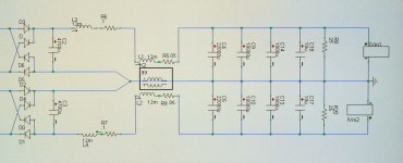
Some time ago I had made the pass-laps idea in a other jacked.
here is the picture, and the board design in ultiboard, out stage used only N-mosfets, and a CCS loaded driver, The CCS I want to change some day, but I will go try this out, it is a lot less consumptional als the real pass labs Class A.
here is the picture, and the board design in ultiboard, out stage used only N-mosfets, and a CCS loaded driver, The CCS I want to change some day, but I will go try this out, it is a lot less consumptional als the real pass labs Class A.
Attachments
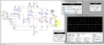
Hey guys, what are the -6db response points for your amps? Mine is 2.6MHz right now. This is an easy test if you have a sine generator, just increase frequency until the response is half of it's ordinary value. (-6db=1/2)
I estimate my VAS miller compensation is about 56pF right now.
Kees, I think that in that amp the upper pair of outputs will be doing most of the work, with the lower pair acting more as a CCS than a push-pull pair. It would be easy to make current sharing more equal by using a bootstrap CCS with a 120R resistor, same as the GS resistor for the lower pair. If you want to tweak the current sharing this could be a trimmer.
If you don't want a bootstrap you could simply add a 120R Vgs resistor to the upper output pair, and increase the CCS current to adjust for the lost current. Then again, you could put a large cap in series with the 120R resistor and leave the CCS as is.
- keantoken
- Status
- Not open for further replies.
- Home
- Amplifiers
- Solid State
- JFET input, MOSFET VAS, LATERAL output = Perfect!!