A lot of diy projects seem to be trying to imitate the 'Oriental style' of p2p ('all right angles, please, and many unsupported connections') or the Fender (guitar amp) style with components neatly lined up on a eyelet/turret board and long connecting wires to tubes and controls.
We really can learn a lot from looking at construction practices from the past, when p2p was the only method of building tube equipment. (I recently read a post where the writer decried the 'messy' wiring on a 50s radio- apparently not enough 90 degree angles in the wiring to suit...)
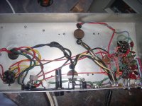
I picked up a console yesterday - nice little 'Chisholm' stereo SE EL84 power amp & PS with the usual remote tuner and phono preamp.
Though they did use the chassis as ground connection, the unit is surprisingly hum-free.
Have a look at the pics, and notice:
-spacious chassis
-power & AC at one end, signal and amp at the other
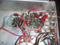
-no unsupported connections
-maximum use of the tube lug connection points
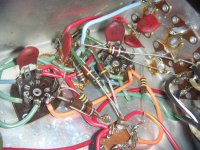
-inputs right at the preamp tube (7025/12AX&) - note the blue and red wires from inputs right to grids (no grid stoppers, but seems to work OK)
-lack of 'wire' used
-tight spacing on the 3 tubes so that resistor and cap leads can span the gap.
We can learn from those guys.....
We really can learn a lot from looking at construction practices from the past, when p2p was the only method of building tube equipment. (I recently read a post where the writer decried the 'messy' wiring on a 50s radio- apparently not enough 90 degree angles in the wiring to suit...)
I picked up a console yesterday - nice little 'Chisholm' stereo SE EL84 power amp & PS with the usual remote tuner and phono preamp.
Though they did use the chassis as ground connection, the unit is surprisingly hum-free.
Have a look at the pics, and notice:
-spacious chassis
-power & AC at one end, signal and amp at the other
-no unsupported connections
-maximum use of the tube lug connection points
-inputs right at the preamp tube (7025/12AX&) - note the blue and red wires from inputs right to grids (no grid stoppers, but seems to work OK)
-lack of 'wire' used
-tight spacing on the 3 tubes so that resistor and cap leads can span the gap.
We can learn from those guys.....
Attachments
If you want to do it "right" I suggest looking at MILSPEC point-to-point wiring. Take a look at some Tektronix oscilloscope modules for example. That stuff's tight! The contraptions you show don't offer much serviceability and as you build them you'll find that it gets harder and harder to get the soldering iron in there without burning things up.
The key is to plan the circuit out on paper first. Take a look at my 6LU8 Spud for example. I'll let you guess which channel was planned on paper first... 🙂

~Tom
The key is to plan the circuit out on paper first. Take a look at my 6LU8 Spud for example. I'll let you guess which channel was planned on paper first... 🙂
~Tom
Also the tubes in the first post seem a bit close together. Doesn't Building Valve Amplifiers suggest 1.5x tube diameter for spacing?
Take a look at my 6LU8 Spud for example. I'll let you guess which channel was planned on paper first... 🙂
Well, first you have to state which channel you think was wired 'better'.....
Also the tubes in the first post seem a bit close together. Doesn't Building Valve Amplifiers suggest 1.5x tube diameter for spacing?
You may be correct. Remember that in a console the tubes are 'in open air' (like most modern diy stuff), not inside a case (e.g. AudioNote, Heathkit!)
The fact that this console has been in regular use for 50 years, still with the original tubes as far as I can tell, should say something to that issue.
I used to teach high school science, and in every class there were students who used to think that the circuits wouldn't work properly unless the connecting leads were bent to show 90-degree corners, as in the schematic.
a.k.a. - "I don't know why my amp squeals and hums; I used lots of wire and laced them all together in neat bundles just like in the 'milspec.' pictures".....
aka "What does it matter if I put 15" of wire between the input jack and the preamp tube on my guitar amp"....
It's amazing how stupid all those people were, building tube 'contraptions' for 40+ years...
Fortunately we can 'get away with 'bad wiring' for most audio projects, so it really doesn't matter.
A little nitpick: I don't consider the Fender eyelet board approach to be "point to point."
The whole idea of "point to point," is that components are wired between , well, points. The Fender uses a part board with wires running to other places. It may be hand-wired, but not point to point.
The whole idea of "point to point," is that components are wired between , well, points. The Fender uses a part board with wires running to other places. It may be hand-wired, but not point to point.
A little nitpick: I don't consider the Fender eyelet board approach to be "point to point."
The whole idea of "point to point," is that components are wired between , well, points. The Fender uses a part board with wires running to other places. It may be hand-wired, but not point to point.
I agree 100%. Same applies to turret board construction, IMO. Turrets individually placed, close to the tubes (Pete Millett's Mighty Midget is a good example) are true p2p - really like individual solder lugs placed where they are needed.
I'm no purist- I've used eyelet & turret for power supply sections, and PCB for regulators, etc. Just more 'tools' for the toolbox.
I just hate to see the 'rat's nest' of wiring or the connections in mid-air that are so common... and commonly admired.
We can learn from those guys.....
Hi,
Or not as the case may be. I cannot see much evidence of good wiring,
e.g. its good to run power supply leads in the corners of the chassis.
Good PtoP wiring layout is as important as PCB layouts, and one of its
advantages is it can be better, a lot better if the component layout
is determined by the wiring issues and not the other way round.
rgds, sreten.
Last edited:
Hi,
Or not as the case may be. I cannot see much evidence of good wiring,
e.g. its good to run power supply leads in the corners of the chassis.
I don't understand.
Except for the heater wiring, there is NO power supply wiring anywhere near the working circuit. Plate resistors come straight off the filter cap, it seems.
Which wires should be running in the corners of the chassis in this example?
I'm eager to learn- do you have an example of better wiring for a circuit like this (2-channel SE)? I need something to study.
Thx.
Good PtoP wiring layout is as important as PCB layouts, and one of its
advantages is it can be better, a lot better if the component layout
is determined by the wiring issues and not the other way round.
I dont understand this either, when laying out a PCB the importance of connections and connectivity determine how you place the components, not the other way round!
Build it as though it is RF, with short direct connections, as the valves don't know they are only supposed to amplify audio. Alternatively, copy a published layout exactly. Don't use long wires like a guitar amp, or tidy wires like military stuff.
Build it as though it is RF, with short direct connections, as the valves don't know they are only supposed to amplify audio. Alternatively, copy a published layout exactly. Don't use long wires like a guitar amp, or tidy wires like military stuff.
😀
Well, that makes two of us, at least!
I think that reading (parts of) 1950's ARRL Amateur radio Handbook when I was 12/13 years old 'messed me up' for modern wiring styles!
If one takes enough care, they can REALLY limit loop length by keeping resistors etc right at the socket.
If one takes enough care, they can REALLY limit loop length by keeping resistors etc right at the socket.
I find it tricky to do in practice, but I'm aiming toward that ideal. Using the center connection point of 9-pin (&7-pin) sockets is another thing that I tend to forget until the project is wired up. Then I see that connection point, and realize that I could have saved going to a terminal strip (and back to the tube).
Not so easy as it looks.....
- Status
- Not open for further replies.
- Home
- Design & Build
- Construction Tips
- Point-to-point wiring done right...