I use schottkys in my CDP but the low voltage ones work better (more silent).
In the phonos I use hexfreds.
Is the MSRF better in any aspect for the phonos.... What about the stealth diodes ?
In the phonos I use hexfreds.
Is the MSRF better in any aspect for the phonos.... What about the stealth diodes ?
diodes...
Stealths and Q-Speeds are good, but the MSRF has a better noise spec, and the MSRF are more affordable as well.
Stealths and Q-Speeds are good, but the MSRF has a better noise spec, and the MSRF are more affordable as well.
pFET for CCS?
Any recommendation of low dropout P-channel MOSFET for CCS? My target is to get 3.3V from 5V source at 200ma. Not sure if Si9433DY is a good choice.
Any recommendation of low dropout P-channel MOSFET for CCS? My target is to get 3.3V from 5V source at 200ma. Not sure if Si9433DY is a good choice.
Last edited:
Its a very high Ciss 2.5W SO-8 part. Will drop PSRR a lot and it won't sink well. Why not modify to a BJT CCS?
Stealths and Q-Speeds are good, but the MSRF has a better noise spec, and the MSRF are more affordable as well.
Pity MSRFs can hold up to 8A, which is not enough for a 100W power amp.
Which type would be best for say 20A or 30A?
MSRF diodes from ON Semi. These are medium speed, super soft recovery diodes and seem to be the most quiet diodes I can find. They are designed with soft recovery being the highest priority, rather than super fast switching (still pretty fast though). I have never understood why people always want the super fast diodes for 50/60 hz AC power supplies, a lot of these super fast diodes have more noise. I use these for line level stuff: the MSRF 860G is a 600V 8A TO-220 style. They also have a nice surface mount version of these (I think those ones are 4 A).
MSR860G is the same like the MSRF860G?
I think the "F" just means it has isolated case and much lower thermal efficiency - suggest 'ordinary' one or step up to the bigger MSR1560G at 15 Amps so even lower "spike" characteristics.
I tried the soft recovery BYW 29 type with the isolated tabs for the F3 and these do unfortunately get quite hot, so larger heatsinks required - same sound, just hotter
- still useful to add the basic R-C snubbers on the bridge output (ref. Hagerman's) - will try the softer MSRs and see.
I tried the soft recovery BYW 29 type with the isolated tabs for the F3 and these do unfortunately get quite hot, so larger heatsinks required - same sound, just hotter
- still useful to add the basic R-C snubbers on the bridge output (ref. Hagerman's) - will try the softer MSRs and see.
yes...
Data sheet:
http://www.onsemi.com/pub_link/Collateral/MSR860-D.PDF
MSR series are the very soft recovery diodes from ON Semi. The "F" is just the insulated case version.
Data sheet:
http://www.onsemi.com/pub_link/Collateral/MSR860-D.PDF
MSR series are the very soft recovery diodes from ON Semi. The "F" is just the insulated case version.
Data sheet:
http://www.onsemi.com/pub_link/Collateral/MSR860-D.PDF
MSR series are the very soft recovery diodes from ON Semi. The "F" is just the insulated case version.

8A should be enough for 100W. I use a soft-start circuit for HFA08TB60 with 264,000uf behind it without problem. The soft-start provides 1~2 seconds delay for charging capacitors. Without it, the HEXFRED will just blown out immediately.
Its a very high Ciss 2.5W SO-8 part. Will drop PSRR a lot and it won't sink well. Why not modify to a BJT CCS?
Is MJE1123 good for BJT CCS?
So, so. A bit slow, drooping gain with current. If you can afford 1V Vbe drop there is MJE15031.
Has anyone here compared the Salas regulator with regs like:
1. ALW super reg
2. Waagbo/Borbely shunt reg?
1. ALW super reg
2. Waagbo/Borbely shunt reg?
Trying to build a 1.2Volt salas shunt for a load of 350mA.... will replacing one of the IRFP9240's with a BD140 or a D45H8 work?
thanks
thanks
It might, but the jFETs will be operating at tiny voltages of less than two times Vp. They do not perform well when the voltage is squeezed that low.
I suspect other opamp controlled shunt regs can perform better.
I suspect other opamp controlled shunt regs can perform better.
what a mess
I do agree that proof is in the pudding, and that ultimately you have to breadboard and measure. The "sound" of a shunt regulator is a long shot since ultimately all circuits can interact. You can hook it to headphones via a blocking cap to listen for noise, that's about it. Pretend you were making a product out of it: measure what belongs in a data sheet. You have to measure things in isolation, then measure the whole system, too.
Nothing beats a good, real life transient response test. Bob Pease lived in the time domain, and that's as good of an approach as any. Bang the input, the output, and various internal nodes, and see what transpires. A network analyzer sweep wouldn't hurt either.
I know that he's been banned and all, but this post is just hilarious. The "position and momentum cannot be determined simultaneously" is true when you're talking about our world on quantum scale. It has nothing to do with circuit simulations. I'd say Lumba is just a troll, nothing more.Right, simply because the variables, position and momentum cannot be determined simultaneously. So simulators are useless for distortion analysis, the results shown are often in opposition, not just to physics, but common sense as well.
Fortunately, there`s no need to simulate straightforward circuits, like shunt regulators.
I do agree that proof is in the pudding, and that ultimately you have to breadboard and measure. The "sound" of a shunt regulator is a long shot since ultimately all circuits can interact. You can hook it to headphones via a blocking cap to listen for noise, that's about it. Pretend you were making a product out of it: measure what belongs in a data sheet. You have to measure things in isolation, then measure the whole system, too.
Nothing beats a good, real life transient response test. Bob Pease lived in the time domain, and that's as good of an approach as any. Bang the input, the output, and various internal nodes, and see what transpires. A network analyzer sweep wouldn't hurt either.
I agree. Both give equivalent results, it's just that we have trouble doing FFTs in our heads. Just looking at a Bode plot may not exactly produce an accurate pulse or step response 😉Hi Ikoflexer, your stability analysis sounds very thorough, well done. Despite phase/gain margin theory I've always felt transient step response to be more revealing
my build
Hi, just to show my salas shunt build that I implemented in my phono stage. Attached is the schematic for the positive regulator. The negative regulator is the same, except for the reversed polarity of the MOSFETs, LEDs, diode and bipolar; otherwise identical.
1) the current source is a degenerated MOSFET, that allows for a nice point for measuring the current, has excellent noise behaviour (much better than LM317 - I tried), and lower voltage drop (the LM317 needs around 3V to start operating properly, this one works at 1V or less voltage differential - 2..3V is better though)
2) The diode in the emitter of the PNP increases the drain voltage of the JFET used as constant current source, making the reference voltage more stable
3) R6=3k3 is on the high side, the current starving for the PNP gives a lowish gain, which combined with the Q3 gain is high enough but still stable.
R8 is zero in my design but may be increased if running into instability. The 1.5uF at the output is all there is.... Output current in my application is 500mA at 12V.
The temperature stability is not great, due to VBE of the PNP decreasing with temperature, and the MOSFET's positive tempco (at least at these lowish currents). It is not helped with the additional diode.
But the drift is not large, and it could be fixed, but then I thought so what. Adjusting the output voltage after thermal settling is good enough. Of course, 10-turn pots for both the current and the voltage are advisable, especially for the current as the adjustment is quite sensitive.
I did measure the output impedance of the shunt regulators with a electronic load that can sink a DC and AC current, and the output impedance (= noise voltage / AC current) was 4mOhm flat from 20Hz to 22kHz. Low and flat, thats what we want right?
hope you like it!
Attachments

OK, a plausible twist of 1.0. But why not current source loads instead R6 & R9? No C across R4&R5? The diode's dynamic impedance degenerates the 2N4403 also.
P.S. Your Zo measured is indeed near the simulator for standard 1.0, was it near the simulation of your particular twists build? Nice opportunity to see how well the modeling follows. Any picture of the prototype?
P.S. Your Zo measured is indeed near the simulator for standard 1.0, was it near the simulation of your particular twists build? Nice opportunity to see how well the modeling follows. Any picture of the prototype?
Hi Salas,
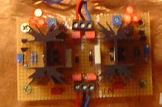
here is a picture, sorry it is not very sharp. This has the positive and negative regulator both on one PCB. In fact, the more I play with it the more I like it! It's a great regulator concept you came up with. All the LEDs should be about the same brightness, this is just my crappy camera misbehaving...
As mentioned over in the other thread, John Curl explained in a lot of detail the use of JFET current sources with resistors as voltage references, and why it matters to not put caps there, and I agree. Might have put a lowpass filter from the voltage reference, but then I didnt and it works just fine.
A current source for the LEDs would have made the thing more stable, no doubt, same for R6. But since I made it all adjustable it works that way just as well. (Honestly, I didnt think about that before you brought it up ;-)))
Actually, I didnt simulate but just built. And yes, I was surprised about these very low values and so we re-did the measurements and verified with other instruments, and yes, that little regulator does the job nicely! The output impedance is flat across the entire frequency range (we only tested up to 22kHz).
When building the phonostage this guy powers, I was using LM317 current sources but the input voltage was too low, and the current source was not operating properly. Although the noise on the output of the phono stage was very low, there was a noticeable bump at 50Hz (+10dB or so), that completely vanished once the current source had enough headroom to operate properly.
Separate sense lines? Yes, that would be nice. Thinking about it.... Guess I have to re-read this thread now ;-)
Attachments
Last edited:
- Status
- Not open for further replies.
- Home
- Amplifiers
- Power Supplies
- The simplistic Salas low voltage shunt regulator