Seriously, are you just trolling or something? Because I have absolutely no idea what you're on about.
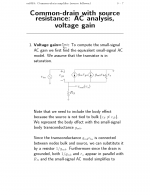
se
se
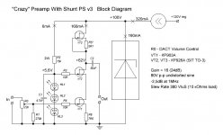
Here is a Block Diagram of the preamp that I specially designed for buffer-like power amps (no voltage gain).
Another fancy parts, SITs in TO-3 case, were used here. The gain and the balance between channels are achieved by parts selection, no NFB used. Zout near 300 Ohms.
Another fancy parts, SITs in TO-3 case, were used here. The gain and the balance between channels are achieved by parts selection, no NFB used. Zout near 300 Ohms.
Attachments
Last edited:
Member
Joined 2009
Paid Member
Bigun,
you didn't say what`s compromised with the cascode.
I'm generalizing, but I understand that active devices add non-linearity and phase shifts to the signal so it's a compromise between these effects and the benefits. I've never used a Cascode so I have no first hand experience to relate to in terms of the impact on the sound.
Here is a Block Diagram of the preamp that I specially designed for buffer-like power amps (no voltage gain).
Another fancy parts, SITs in TO-3 case, were used here. The gain and the balance between channels are achieved by parts selection, no NFB used. Zout near 300 Ohms.
Finally, something I can make some sense out of! 😀
se
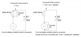
WuYit,Without further explanation, it has been claimed that the statement that class A amplifiers biased with a constant current source draw constant current from the power supply is wrong, even more mysteriously, with the exception of the design of this thread.
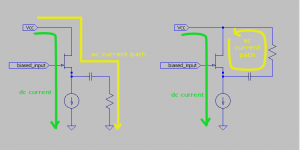
When a CCS is the only element connected to power or ground in a circuit, the power-supply draw will be constant (in the ideal). However, the typical follower circuit on the left is class-A single-ended biased with a CCS, but the current draw from the supply is not constant (all AC current to the load is drawn directly from the supply). In contrast, the variation of the OP (and Ciuffoli), on the right, does draw constant current from the supply (having only a single CCS to ground). Everyone, including me, has simply been pointing out this distinction to you.
Attachments

thune,
not making a clear distinction between AC and DC properties and functions, I find your description to be extremely muddy. Anyway, there is no difference between the circuits from a constant current point of view.
not making a clear distinction between AC and DC properties and functions, I find your description to be extremely muddy. Anyway, there is no difference between the circuits from a constant current point of view.
WuYit,
I really don't know how to break it down more clearly, except maybe to add the DC current flow to the graphic and appeal to its properties. Understanding that 'total current=dc current + ac current' at any 'edge' in the circuit graph: We see that the left circuit has varying current drawn from the supply (DC+AC) while the circuit on the right has only unvarying current (DC) drawn from the supply.
If this explanation is still too muddled, I recommend reviewing Kirchkoff's circuit laws, and the concept of superposition.
Attachments
Andrea is correct.
The leftmost diagram is not constant current. The rightmost diagram is essentially constant current.
Almost all SE ClassA (buffer) stages adopt the leftmost diagram.
Use of the rightmost diagram is extremely rare.
Thune,
it seems Wuyit is refusing to listen to reason and explanation.
The leftmost diagram is not constant current. The rightmost diagram is essentially constant current.
Almost all SE ClassA (buffer) stages adopt the leftmost diagram.
Use of the rightmost diagram is extremely rare.
Thune,
it seems Wuyit is refusing to listen to reason and explanation.
Last edited:
I have already disputed with WuYit this shunt-load-to-active-device specifity in another thread, also by presenting drawings and verbal explainations. Nothing had any effect. I concluded there is something subjective or personal, from WuYit side, to this approach. His position is hardly understandable. Maybe it's a way to get some popularity by acting as a "specific" guy.
Last edited:
I too wrote to Wuyit privately trying to explain where his reasoning had gone wrong. He appeared to have ignored that PM.
Should we ask that the Moderating team respond if Wuyit repeats his erroneous claims without a reasoned and logic explanation accompanying that claim?
Repeating of (erroneous) information is not permitted on this Forum !
Should we ask that the Moderating team respond if Wuyit repeats his erroneous claims without a reasoned and logic explanation accompanying that claim?
Repeating of (erroneous) information is not permitted on this Forum !
Last edited:
Hi,
to avoid including an accuracy aspect, we assume that the CCS`s are perfect. In both circuits, the same amount of DC current flows through the amplifying device and the CCS, determined by the CCS, not changing or exceeding its value. It is the total current. A portion of it is converted to AC for the load (and will be used up), an affair strictly between the amplifier and the load, not seen by the power supply. While the DC current is constant, the AC power is anything but constant, all values are instantaneous. Kirchhoff's Law and other laws apply, but not needed for the explanation, everything is straightforward.
to avoid including an accuracy aspect, we assume that the CCS`s are perfect. In both circuits, the same amount of DC current flows through the amplifying device and the CCS, determined by the CCS, not changing or exceeding its value. It is the total current. A portion of it is converted to AC for the load (and will be used up), an affair strictly between the amplifier and the load, not seen by the power supply. While the DC current is constant, the AC power is anything but constant, all values are instantaneous. Kirchhoff's Law and other laws apply, but not needed for the explanation, everything is straightforward.
Hi,
to avoid including an accuracy aspect, we assume that the CCS`s are perfect. In both circuits, the same amount of DC current flows through the amplifying device and the CCS, determined by the CCS, not changing or exceeding its value. It is the total current. A portion of it is converted to AC for the load (and will be used up), an affair strictly between the amplifier and the load, not seen by the power supply. While the DC current is constant, the AC power is anything but constant, all values are instantaneous. Kirchhoff's Law and other laws apply, but not needed for the explanation, everything is straightforward.
This is another one variant of explainations. If WuYit accepts this, many will be happy
Attachments
Last edited:
Not to interrupt, but am I correct that a quiet PSU is VERY important in this amp.
Not exactly, since the PS ripples are eaten by the high dynamic impedance of the PS
- Status
- Not open for further replies.
- Home
- Amplifiers
- Solid State
- jFET Power Buffer