Wahab, yes the triple is a bit unusual but not unknown in a big amp like this.
I agree the idea of a MOSFET output stage is appealing and it's certainly simpler.
The mosfet stage is just as prone to parasitic' s as a triple. I noticed you have none of the stability "trick's" incorporated in your amp. Perhaps you "lucked out" with the low Ft 21193/4's and survived for a while because of this. No such luck with 30 Mhz devices.


It might work well normally , but approaching the rails - maybe not 😱 .
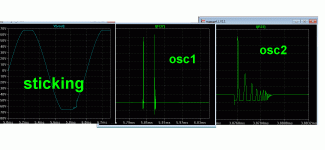
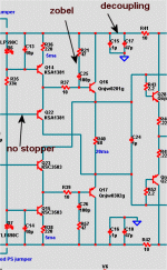
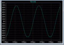
(below 1) is what happens both in simulation and on the real one. Clip the amp , predrivers saturate - "stick" , producing oscillations. (below 2) is how the OEM's deal with this "behavior". (below 2 - #1) is the APT , it is actually the only perfect solution .... diode clamps stop saturation and eliminate "sticking". APT's OPS devices are also low Ft , further mitigating any bad "behavior". #2 is the HK triple , no clamping .. this amp will "stick" (saturate). HK uses a inductive filter at the bases of the outputs. A driver B-C zobel network will do the same thing, as I will show later. #3 , JVC uses separate driver/predriver decoupling (in Cordell's book) and a B-C shunt stopper on the predriver.
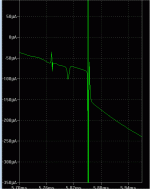
(below 3) is the best combination of "tricks". I show Cordell's "DBT" , but this can be applied to any triple. (below 4) shows worst case severely clipped former oscillation very damped by the combo of decoupling and zobel. An EF2 will also exhibit these errata's if high beta (2sc4793-2sa1837 + mjl4302-4281).
The MOSFET's are nice , I have 2 pair of the original Hitachi TO-3's (K134-J49). Actually used a MJE340/350 pair as drivers and 470R gatestoppers - worked first time... 🙂. For a permanent solution , I would choose 2sc4793-2sa1837 and 3 pair K1058/J162.
OS
Attachments
Update. When I mentioned that speakers sounded different, it was because I had hooked them up to my Marantz PM7000 for a quick listen. Well last night I swapped the speaker connections over on the Marantz. Turns out the speakers (after the bass unit replacement) are 100% ok. It's the Marantz that is playing up. Looks like this new house I am in is jinxed for amps!
I'm curious as to what led to your amps blowing up and what's affecting your Marantz. Is it something in the Mains Line or perhaps high RF?
Ostripper,
I have exactly the stability tricks you point out in my amp. Without the base networks and the decoupling, the triple is not stable. I've looked at quite a few options here and how the driver and output behaves at HF. Bob proposes a Zobel network across the base and collector of the driver. I used an L section in the base of the driver. I also found that at HF (hundreds of KHz), a large speed up cap across the pre drver emitter resistor helps reduce cross conduction in the driver stage. So, there are actually two distinct problems to deal with here (they may be linked, but that would need more work to prove it). I have tried the ferrite in the bases, but my selection was linked to what was available in the sample bin. On sims, it seems to offer some real benefits, killing HF instability and dealing with cross conduction.
Re the mosfets. Yes they are also prone to instability but my point was they are simpler to use in an output stage. Probability a straight gate stopper and good rail decoupling will be enough.
Last edited:
Interesting question Michael. The mains here varies between 110 and 117. I am not sure about HF yet, I need to make sure about it though.
The Marantz sat in my loft in Tokyo through a summer and a winter. That may also have something to do with it. I hope to have some time this weekend to look at it.
The Marantz sat in my loft in Tokyo through a summer and a winter. That may also have something to do with it. I hope to have some time this weekend to look at it.
I have exactly the stability tricks you point out in my amp.
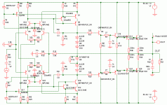
?? Are we talking different amps? http://hifisonix.com/wordpress/wp-content/uploads/2010/10/Ovation-250-Schematics.pdf
I don't see any. BF - xxx / MJE/MJL ... straight triple. It is lower beta triple (50-50-30 Hfe). Not saying it is improperly designed , but it is what it is and must be dealt with.
OS
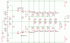
Bonsai , looking at your schematic, it seems that the design goal
is to achieve a 20KHZ OL bandwith , but this is done by reducing
the gain below this frequency , using a pair of parraleled 15K resistors.
The only result is to reduce NFB below 20khz and thus to have
a constant but increased THD vs frequency.
The standing current are out of proportion with the usual designs.
The differential pair drain about 10mA , wich seems to me excessive,
as well as the common base parts of the two VAS that conduct 20mA;
wich is uselessy high since it s followed by a triple EF.
This latter s pre-driver iddle current is also quite high, leading
to thermal dissipation dangeourously close to the transistors ratings.
Also , the driver s dissipation is high as well..
All in all, the choice of high standing current mandate generous
heatspreaders for the relevant devices to ensure enough reliability,
wich, given the price of good speakers , should be the number one
concern when designing an amplifier, moreover if it s a high power one.
Attachments
Last edited:
Wahab , what is C4/C2 in your second attachment ? 1n shunt to earth ?
One of the reasons I want a triple. I can run the VAS at 3-5ma , use my resistive shunts to trim OLG without worrying about loading of the the output stage , and be able to use a high impedance cascoded voltage stage. Running cool devices will make for 15 years of fault free service (MTFB).
The pre-driver only buffers the VAS from the drivers , does not need much more than 6-8ma , even to drive outputs used as drivers. I see technically - Bonsai's reason for high driver current. At 40-50ma , carrier "suckout" from the OP's is optimal. BUT , the MJE's are borderline .... I use small sanken to-3p outputs for drivers (a1294/c3264) , they actually could run without heatsinks.
The "choices" are -
- MOSFET drivers with BJT OPS - VAS has to drive gate capacitance and you lose Vgs from the rails.
-BJT drivers with lateral OPS - by far the best but more expensive , VAS would just see small Cob of a good driver pair and OP's would sound wonderful - NO Vbe as well.
-BJT EF2 - high biased VAS (10-12ma) , lower current MJE drivers - High Hfe outputs. Still limited "arc welder" ability 😀 Unlike DX , I would never do more than 4 pair OP's - "droop" city !!
-And the Triple. Harder to layout and stabilize , DBT loses 2.1v from rails and the Locanthi triple 2.4v. 3 vbe's need to be compensated for (DBT = 1 Vbe).
But it is cheap (BJT's) and I have seen 20 year old units that survive (It can be done).
That is very subjective - what is "overcomplicated" ? We should all build fetzilla's , DX's , or pass amps ? ANY amp can oscillate ! This is why we have CRO's and simulators. 😱
OS
The standing current are out of proportion with the usual designs.
The differential pair drain about 10mA , wich seems to me excessive,
as well as the common base parts of the two VAS that conduct 20mA;
wich is uselessy high since it s followed by a triple EF.
One of the reasons I want a triple. I can run the VAS at 3-5ma , use my resistive shunts to trim OLG without worrying about loading of the the output stage , and be able to use a high impedance cascoded voltage stage. Running cool devices will make for 15 years of fault free service (MTFB).
This latter s pre-driver iddle current is also quite high, leading
to thermal dissipation dangeourously close to the transistors ratings.
Also , the driver s dissipation is high as well..
The pre-driver only buffers the VAS from the drivers , does not need much more than 6-8ma , even to drive outputs used as drivers. I see technically - Bonsai's reason for high driver current. At 40-50ma , carrier "suckout" from the OP's is optimal. BUT , the MJE's are borderline .... I use small sanken to-3p outputs for drivers (a1294/c3264) , they actually could run without heatsinks.
The "choices" are -
- MOSFET drivers with BJT OPS - VAS has to drive gate capacitance and you lose Vgs from the rails.
-BJT drivers with lateral OPS - by far the best but more expensive , VAS would just see small Cob of a good driver pair and OP's would sound wonderful - NO Vbe as well.
-BJT EF2 - high biased VAS (10-12ma) , lower current MJE drivers - High Hfe outputs. Still limited "arc welder" ability 😀 Unlike DX , I would never do more than 4 pair OP's - "droop" city !!
-And the Triple. Harder to layout and stabilize , DBT loses 2.1v from rails and the Locanthi triple 2.4v. 3 vbe's need to be compensated for (DBT = 1 Vbe).
But it is cheap (BJT's) and I have seen 20 year old units that survive (It can be done).
By PMA - Overcomplicated power amplifier designs are prone to HF oscillations under critical conditions
That is very subjective - what is "overcomplicated" ? We should all build fetzilla's , DX's , or pass amps ? ANY amp can oscillate ! This is why we have CRO's and simulators. 😱
OS
Wahab , what is C4/C2 in your second attachment ? 1n shunt to earth ?
Hi, OS
Well, that s some kind of cell to limit high frequency response,
but i suppose that Bonsai can explain to what extent it is needed
to improve stability.😕
That is very subjective - what is "overcomplicated" ? We should all build fetzilla's , DX's , or pass amps ? ANY amp can oscillate ! This is why we have CRO's and simulators. 😱
OS
Surely that he means too much stages is an incentive to instable amp,
but then Bonsai s design only has the pre-driver as an extra stage compared
to the usual designs..
Indeed, missing compensations caps , as in PMA s SS amp , is also
a risky choice in matter of stability , despite this design having
a more usual and stable double EF output stage...🙂
?? Are we talking different amps? http://hifisonix.com/wordpress/wp-content/uploads/2010/10/Ovation-250-Schematics.pdf
I don't see any. BF - xxx / MJE/MJL ... straight triple. It is lower beta triple (50-50-30 Hfe). Not saying it is improperly designed , but it is what it is and must be dealt with.
OS
The 27 ohm and the 1n cap is the comp network. You can use this technique OR you can use an RC network between the base and the collector of the driver.. Remember for AC analysis, if your supplies are decoupled or fed rom a standard rectifier/capacitor PSU the supply rails for AC are the same as ground. That's why you sometimes also see this network (RC) connected between the base and ground. The network I used came from an app note issued by micro cap years ago. Unfortunately I don't have it anymore.
Last edited:
Wahab,
You need to read the accompanying notes for the detail. The boards are a little different to the schematic. I probably need to update it and post it up.
The 15k resistors are shown on the circuit. They were removed long ago from the board (three years ago in fact). The output inductors were rewound for 2uH, again long ago. Some people recommend removing the inductors or going with a very low vale like 1uH. Because I am using slow output devices, I was concerned with possible instability into cap active loads. The inductor Value I selected is therefore 2uH.
This design does not use a mirror loaded LTP so the tail current has been deliberately set to 5mA per side. With the degeneration and comp caps shown, the amp is very fast (ie slew rate) and is absolutely TIM free. These were the design goals.
Re the standing currents in the VAS and pre drver stage. If you do a sim into worst case load conditions, you will see that running these stages hot helps the performance. I also had a brief exchange with Bob Cordell on this forum, and he apparently also likes to run his pre and drver stages hot, though not quite as much as me.
Last edited:
I don't think running cool necessarily translates to longer life. There are many applications where components routinely at high temperatures for extended periods. Modern semi's are fully characterized for this kind of environment. The VAS and pre-drivers are on heatsinks BTW.
That is very subjective - what is "overcomplicated" ? We should all build fetzilla's , DX's , or pass amps ? ANY amp can oscillate ! This is why we have CRO's and simulators.
Agree!!
Agree!!
Nicely drawn circuit Wahab, but you need to show the rail decoupling (100uF from rails to GND) along with the 1uF stacked foils. The input stage up to the VAS is isolated from the driver and output through 1A diodes.
I will update the circuit on my page after repairing and implementing the TMC compensation. By the way, this sims out at 11ppm at 20kHz at 40V peak output into 8 ohms. I see no need with this design to go for a mirror loaded LTP because it's in the ball park distortion wise.
I will update the circuit on my page after repairing and implementing the TMC compensation. By the way, this sims out at 11ppm at 20kHz at 40V peak output into 8 ohms. I see no need with this design to go for a mirror loaded LTP because it's in the ball park distortion wise.
Wahab,
You need to read the accompanying notes for the detail. The boards are a little different to the schematic. I probably need to update it and post it up.
This design does not use a mirror loaded LTP so the tail current has been deliberately set to 5mA per side. With the degenerate and comp caps shown, the amp is very fast (ie slew rate) and is absolutely TIM free. These were the design goals.
Re the standing currents in the VAS and pre drver stage. If you do a sim into worst case load conditions, you will see that running these stages hot helps the performance. I also had a brief exchange with Bob Cordell on this forum, and he apparently also likes to run his pre and drver stages hot, though not quite as much as me.
Will do some sims to see the caracteristics , but anyway, the schematic
is a very pleasing, for my liking, symetrical differential, and about this
exact topology, i m almost sure PMA will applaude as well..😉
As for running hot , well, one can suppose that Bob means at high current
and thermal dissipation , but not sure that it means litteraly at high temperature ,
wich would undoubtly increase the devices gains....😕
I just took a look, my comp caps are shown as 22pf on the circuit and are 47pf on the board.
Re the temperature. All the components pass Bob's finger test, so nothin is above about 65C.
'running hot'
yes, what I mean is running at high current and not high temperature.
Re the temperature. All the components pass Bob's finger test, so nothin is above about 65C.
'running hot'
yes, what I mean is running at high current and not high temperature.
Re rail sticking. This amp does not have this problem and exits clipping cleanly and without any parasitics or sticking. The biggest cause of at king in most amp is in the mirror and/or if slow devices are used in the VAS stage. The Ovation uses resistive LTP loading, so no sticking there, and the VAS amp is cascaded with BF4xx devices which are very fast and come out of saturation very quickly. My first design about 10 years ago used MJE350/340 and a single ended mirror loaded front end and this had a lot of issues similar to the ones you show Ostripper. Only way out was to go to fast VAS devices and to use anti saturation diodes.
I don't think running cool necessarily translates to longer life. There are many applications where components routinely at high temperatures for extended periods. Modern semi's are fully characterized for this kind of environment. The VAS and pre-drivers are on heatsinks BTW.
Not to be contrary , but it does. Google "semiconductor MTBF vs. temperature" and you will find this not only to be true , but some manufacturer's actually specify the temp./power derating vs. the MTBF in graph form.
SOA also is greatly reduced with high temperature . 🙁
As a secondary consideration , greater heat produced by the semi's will also shorten the life of the passive components that share the same enclosure.. Electrolytic's are also derated (hrs. @ degrees C) according to operating temperature. A MJE15032's Pd increases by 50% from 65C to 35C (below).
Your nice amp was a inspiration for me to go ahead with mine , I agree on your "hot" driver concept (40-60ma bias) and that a push pull VAS DOES have a better sound than a LIN setup. I just want to over-engineer the driver stage with to-3p's (even 60ma will barely heat them up to 40C - without a HS !)
OS
Attachments
Re rail sticking. This amp does not have this problem and exits clipping cleanly and without any parasitics or sticking. The biggest cause of at king in most amp is in the mirror and/or if slow devices are used in the VAS stage. The Ovation uses resistive LTP loading, so no sticking there, and the VAS amp is cascaded with BF4xx devices which are very fast and come out of saturation very quickly. My first design about 10 years ago used MJE350/340 and a single ended mirror loaded front end and this had a lot of issues similar to the ones you show Ostripper. Only way out was to go to fast VAS devices and to use anti saturation diodes.
"Sticking" , I have only seen in simulation and heard it mentioned in the forum. On a CRO , I never have seen the errata observed in my previous plots. I may even be chasing "ghosts" here. I downloaded Cordell's models (below) for the ON/fairchild devices and now my simulations are much closer to the real amp. I may be actually overdesigning to compensate for bad models ? 😕
PS - below 2 , same triple ... but with cordells 1381/3503 models , clean clip
OS
Attachments
Last edited:
Ostripper, I don't doubt your info, but as I noted all my devices pass the BC finger test. Of course i agree on the SOA point. I worked in auto semis for about 5 years and an ECU regularly goes to 80 or 90 with individual comps even higher that this. If you look for example at automotive specified mosfets you will see they are characterized for extreme temperatures, and some parameters guaranteed to 175 C. The issue with high temp is mainly around the temp cycling that stresses the die to header interface solder and bond wire connections and one of the reasons semis for this segment go through very strenuous quake tests. A lot of that technology and know how, especially in companies that are involved in both auto and consumer, is used to impove overall product reliability. That said, don't ever exceed the data sheet ratings because an upshot of all of this has been that semis specs are very close to their limits - the tight process controls and device and materials knowledge mean suppliers have a good bead on the device performance envelope and spec accordingly.
Last edited:
Re sticking, I could make it happen in the sims with the MJE340/50 models. I get no sticking now in practice and in the model. I will try to post up some pics in the next few days.
- Home
- Amplifiers
- Solid State
- Output Relays
