hello sir ...
u can use 100pf/1kv nd 10nf/1kv...
thank u...
__________________
Aman....
Hello Sir ,
Thanks for the response.
Is it ok to use 50v rating for c2 and c5 ? I want to know the voltage drop across 100pf and 10nf when using +/- 70Vdc supply, have you tried to measure it Sir?
regards
apex,
using tripple darlington,
with 12 output pair,
and 5200/1943 driver, what is the max supply?,
and how much resistance/ohms load can handle?,
how much power/watts?
using tripple darlington,
with 12 output pair,
and 5200/1943 driver, what is the max supply?,
and how much resistance/ohms load can handle?,
how much power/watts?
Attachments

Last edited:
Maybe he has a bunch of those caps and wants to get rid of them. 😉
reason enough for me...😀
add up your rails..... so if you are using =/-75volts say, you can use 150 volt rated caps if you can find them.....
here is some reference: RF Cafe - Standard Capacitor Values
Hello Sir ,
Thanks for the response.
Is it ok to use 50v rating for c2 and c5 ? I want to know the voltage drop across 100pf and 10nf when using +/- 70Vdc supply, have you tried to measure it Sir?
regards
yes for C2/C5.....
the voltage drop across the 100pf depends on the base-collector voltage of the trannie they connect to....no point in measuring the voltage drop accros them....
these capacitors are needed for frequency stability....you can use 600 or 630volt rated caps for these as they are available in manila...
Preamp Balance to Unbalance with Limiter and Bridge Mode
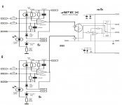
Hi apex, I try to incorporate some of the circuit that you share on this forum, I made the circuit as shown. My plan will create BALANCE TO UNBALANCE preamp with limiter and Bridge Mode.
My question:
1. whether the circuit that I made is correct?
2. for the Clip LED, whether componen value should be changed?
3. what is the function of the 10K resistors circled in the circuit Bridge.
usually for Bridge presence on Channel A. I listened to this series of Channel B is the Bridge mode.
4. I wear Voltage 15V CT.
Help me Mr. APEX is a series that I created is correct?
We are in the Corrections and given an explanation on what to do.
Regards.
Attachments
Last edited:
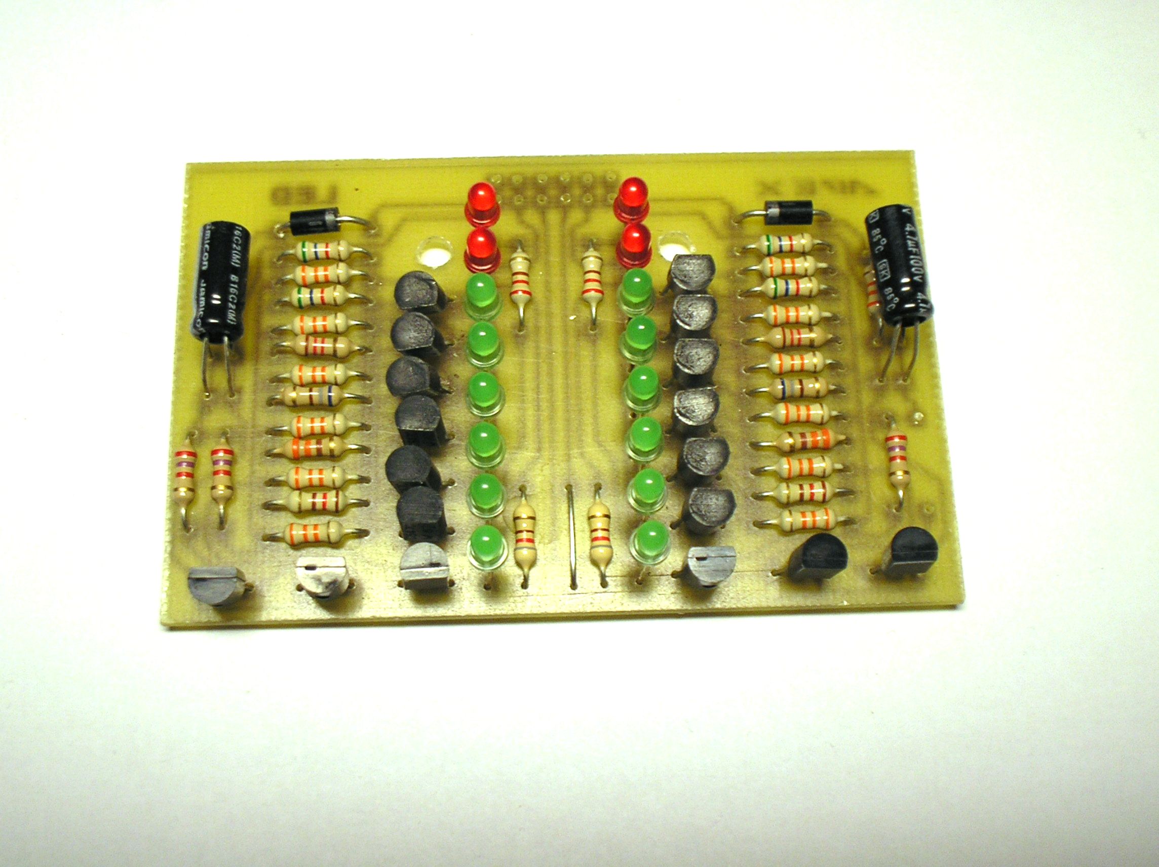
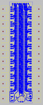
sir can u tell me wht is the exact size of this b500 easy kit?pls n tnxHi aman khalsa and all.
Thank you aman khalsa for final check B500 easy drive and i corrected for PCB.
Regards.
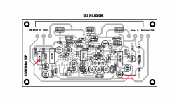
This Regulated PSU can be use for B500.
Sir, Can I have the pcv layout and size of this regulater psu?
This is recomended protect.
Mr. for a list of components can be displayed?
Last edited:
pls help.
after powering my b500 speaker giving big sound ,so what should i do.
also giving hum sound and also click sound,when i power off with reduce volume the speakers giving big sound.
after powering my b500 speaker giving big sound ,so what should i do.
also giving hum sound and also click sound,when i power off with reduce volume the speakers giving big sound.
i have a trafo from a dead amp...and still working fine...but i dont know how many amperes it was....until i read this ohm's law,im not pretty sure but my basic math says it was around 26amp...because on the back of amp housing it was indicated that 5000w max input......the output is 96v-0-96v....96+96 x 26amp6= 4992......did my figure is correct.....pls correct me...if i didnt get right computation...thanx a lot
anybody pls help.
when i power on the amp it giving big sound like (top), same sound coming when i power off. so pls help. amp sound is fantastic.
when i power on the amp it giving big sound like (top), same sound coming when i power off. so pls help. amp sound is fantastic.
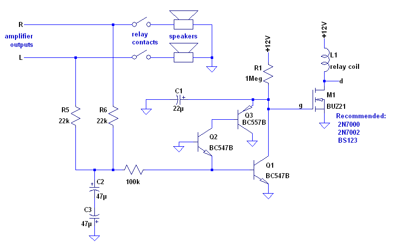
Thats normal, its called a turn on/off thump and is caused by rc time constants at the ltp inputs due to the input and feedback cap beeing a different size and thus take different time to charge up.
Why you don't hear it in commercial amps is because of the delay in the speaker dc protect circuit on turn on.
I built this speaker dc protect circuit and its working nicely:
Why you don't hear it in commercial amps is because of the delay in the speaker dc protect circuit on turn on.
I built this speaker dc protect circuit and its working nicely:
Last edited:
Thats normal, its called a turn on/off thump and is caused by rc time constants at the ltp inputs due to the input and feedback cap beeing a different size and thus take different time to charge up.
Why you don't hear it in commercial amps is because of the delay in the speaker dc protect circuit on turn on.
I built this speaker dc protect circuit and its working nicely:
thanks tekko for the reply.
but in nmos amps i didnt hear that sounds. why is that?
do u have the pcb of the dc protect ciurcuit.
Any PCB Layout for this schematic?I have modified Apex B500, now its B500 NMOS AMP
Attachment schematic
- Home
- Amplifiers
- Solid State
- 500W PA amplifier with Limiter