Mooly: It's instructive to stick a spectrum analyzer on the output of the servo to see what AC residual you have.
I haven't got an audio spectrum analyser... have an RF one but it doesn't go low enough.
I guess you could amplify the output of the servo and examine it perhaps...
Hi,
I am not Sy.
However, if implemented sufficiently hamfisted, Servo circuits can produce significant levels of AC on the output of the servo-op-amp (even up to clipping). And as this AC signal is coupled into the signal circuit somewhere such a signal CAN have audible effects.
Ciao T
SY, you are not suggesting that any unwanted spectrum from the op-amp servo output may affect the sound quality perceived?
I am not Sy.
However, if implemented sufficiently hamfisted, Servo circuits can produce significant levels of AC on the output of the servo-op-amp (even up to clipping). And as this AC signal is coupled into the signal circuit somewhere such a signal CAN have audible effects.
Ciao T
If you have a soundcard, you have a spectrum analyzer. 😀
OK OK OK...
😛
Typing on 4.5 year old laptop.......
Hi,
I am not Sy.
However, if implemented sufficiently hamfisted, Servo circuits can produce significant levels of AC on the output of the servo-op-amp (even up to clipping). And as this AC signal is coupled into the signal circuit somewhere such a signal CAN have audible effects.
Ciao T
Perhaps I was looking for something more subtle, but this is no more than basic electronics.
Of course if the integrator / filter parameters have a roll-off that is significant in the bandwidth of interest it will - err - have significant effects within that bandwidth!
This is little different to the efects of the series C , Rin corner in a none servoed voltage feedback.
And to suggest that a servo output of < 3v (if that is what you did suggest) requires further tweaking is mis-leading. Perhaps if this is a one-off, but for production the server must accomodate the worst-case total offset error. The case in question might be "lucky" and have near zero uncorrected offset anyway.
Until a semi is changed a few years down the line ....
But mabe I am missing something ...
Hi,
Surely this basic electronics more than suffices for potentially audible effects?
Correct, except we now have an additional active element and the potential for gain or attenuation in the circuit.
First, the item being discussed is a DIY one-off, secondly, my worked out example illustrated the "worst case" approach quite well.
Ciao T
Perhaps I was looking for something more subtle, but this is no more than basic electronics.
Surely this basic electronics more than suffices for potentially audible effects?
This is little different to the efects of the series C , Rin corner in a none servoed voltage feedback.
Correct, except we now have an additional active element and the potential for gain or attenuation in the circuit.
And to suggest that a servo output of < 3v (if that is what you did suggest) requires further tweaking is mis-leading. Perhaps if this is a one-off, but for production the server must accomodate the worst-case total offset error. The case in question might be "lucky" and have near zero uncorrected offset anyway.
First, the item being discussed is a DIY one-off, secondly, my worked out example illustrated the "worst case" approach quite well.
Ciao T
Thorsten, you obviously understand the implications of what SY was suggesting to test for.
However about it sufficing I would suggest depended on the resolution of the design.
However about it sufficing I would suggest depended on the resolution of the design.
Last edited:
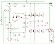
Hi all.
Kevin Gilmore has made a interesting DC-servo in his headphone amp. He is manipulating the current sources of the input stage. Very elegant!
powerpill.org
Kevin Gilmore:Servo loops MUST NOT be in the audio feedback loop. This rule is also very important. Two of my favorite high-end audio electronics manufacturers put servo loops into the minus input of their amplifiers. Most other manufacturers that use servo loops do the same thing. Opamps used for servo loops do not have an output impedance low enough to make them suitable for this purpose. Furthermore the dynamic output impedance of opamps adds non-linearities to the audio when put in series with the gain resistor on the minus input.
What is your opinion?
Regards
GEirin
Attachments
Hi,
Yes. And I feel that it is insufficient to cover all bases, but it is a start. It also much depends on soundcard used for the measurements.
In addition to an AP2 I use a EMU 1616m, it has quite low noise Microphone Amplifiers which can be used to give extra gain and make stuff measurable that would otherwise be lost in the AD converters limited dynamic range.
In the end, setting the cutoff of the servo very low (if neccesary with circuits to speed up settling) will minimise the gain at frequencies that the amplifier will operate at.
Minimising the (AC) gain for the output of the Servo minimises that impact of any non-ideal properties of the Servo, (be it noise, signal feed through etc.). This may mean not returning the Servo Output into the feedback node (often the VAS output may be the right place)...
Selecting a suitable low noise, high linearity Op-Amp minimises any non-ideal properties of the Servo Op-Amp and selecting a high quality film capacitor (watch microphonics especially) minimises it's non-ideal properties.
So all of these generally constitute "common sense" IMNSHO in the relative in which I have placed them, that is correct circuit design first, exotic components last.
In practice a TL072 and a 1uF/63V Wima MKP Cap can perform quite well, if implemented correctly. In my case the with the above the servo voltage is not injected directly into a audio node and is filtered with 10/2,200uF (the subject is an MC level input stage in this case).
Ciao T
Thorsten, you obviously understand the implications of what SY was suggesting to test for.
Yes. And I feel that it is insufficient to cover all bases, but it is a start. It also much depends on soundcard used for the measurements.
In addition to an AP2 I use a EMU 1616m, it has quite low noise Microphone Amplifiers which can be used to give extra gain and make stuff measurable that would otherwise be lost in the AD converters limited dynamic range.
In the end, setting the cutoff of the servo very low (if neccesary with circuits to speed up settling) will minimise the gain at frequencies that the amplifier will operate at.
Minimising the (AC) gain for the output of the Servo minimises that impact of any non-ideal properties of the Servo, (be it noise, signal feed through etc.). This may mean not returning the Servo Output into the feedback node (often the VAS output may be the right place)...
Selecting a suitable low noise, high linearity Op-Amp minimises any non-ideal properties of the Servo Op-Amp and selecting a high quality film capacitor (watch microphonics especially) minimises it's non-ideal properties.
So all of these generally constitute "common sense" IMNSHO in the relative in which I have placed them, that is correct circuit design first, exotic components last.
In practice a TL072 and a 1uF/63V Wima MKP Cap can perform quite well, if implemented correctly. In my case the with the above the servo voltage is not injected directly into a audio node and is filtered with 10/2,200uF (the subject is an MC level input stage in this case).
Ciao T
Hi all.
Kevin Gilmore has made a interesting DC-servo in his headphone amp. He is manipulating the current sources of the input stage. Very elegant!
powerpill.org
Kevin Gilmore:Servo loops MUST NOT be in the audio feedback loop. This rule is also very important. Two of my favorite high-end audio electronics manufacturers put servo loops into the minus input of their amplifiers. Most other manufacturers that use servo loops do the same thing. Opamps used for servo loops do not have an output impedance low enough to make them suitable for this purpose. Furthermore the dynamic output impedance of opamps adds non-linearities to the audio when put in series with the gain resistor on the minus input.
What is your opinion?
Regards
GEirin
Hello GEirin
Why do you need a servo for the circuit you have posted.
Regards
Arthur
Hi all.
The circuit I posted is the Kevin Gilmore amplifier, not mine. My intention is to know the opinion about this type of servo.
The circuit I posted is the Kevin Gilmore amplifier, not mine. My intention is to know the opinion about this type of servo.
Hi all.
The circuit I posted is the Kevin Gilmore amplifier, not mine. My intention is to know the opinion about this type of servo.
Hello GEirin
Why dont you build it and compare you definetly will learn something from the experience. Kevin makes a few claims , but he never proves for example how >>
the opamp's dynamic output impedance adds non-linearities to the audio when put in series with the gain resistor on the minus input.
with actual measurements.
Regards
Arthur
Suggested Thread Split
Hi,
It seems some wish to deviate from stated aim of this thread, namely to debate how one may maximally optimise DC Servos (perhaps well beyond what may seem to necessary to avoid audible problems), instead they wish to debate why or why not DC Servo's may or may not have any audibile or measured effect.
It seems these aims are better served in two separate threads, rather than co-mingling them.
Ciao T
Hi,
Kevin makes a few claims , but he never proves for example how >>
the opamp's dynamic output impedance adds non-linearities to the audio when put in series with the gain resistor on the minus input.
It seems some wish to deviate from stated aim of this thread, namely to debate how one may maximally optimise DC Servos (perhaps well beyond what may seem to necessary to avoid audible problems), instead they wish to debate why or why not DC Servo's may or may not have any audibile or measured effect.
It seems these aims are better served in two separate threads, rather than co-mingling them.
Ciao T
Last edited:
but he never proves for example how the opamp's dynamic output impedance adds non-linearities to the audio when put in series with the gain resistor on the minus input with actual measurements.
It's not hard to set up a more conventional type of servo that doesn't add anything significant to the audio signal, so I think it's a solution to a non-existent problem. But if the designer has measurements showing otherwise, that would be interesting to see. The link took me to a blank page...
It is a bunch of bull...Kevin Gilmore:Servo loops MUST NOT be in the audio feedback loop. This rule is also very important. Two of my favorite high-end audio electronics manufacturers put servo loops into the minus input of their amplifiers. Most other manufacturers that use servo loops do the same thing. Opamps used for servo loops do not have an output impedance low enough to make them suitable for this purpose. Furthermore the dynamic output impedance of opamps adds non-linearities to the audio when put in series with the gain resistor on the minus input.
What is your opinion?
Regards
GEirin
1. The DC feedbak will be in the "loop" no matter what, otherwise it doesn't work. Attaching it in some other point of the feedback loop doesn't change nothing.
2. The influence that it has on the loop is in DC and very low frequency range because the rectification and filtering. That puts the resultant low-pass filter frequency below 0.2-1Hz.
Can it be done better than with an OpAmp PI stage? Nope... you don't need a PID for fast loops. It is a basic PID controller loop and is not rocket science to understand it.
3. "OpAmps do not have an output impedance low enough ". To do what? To drive a 10-100kohm input??? Is he serious?
Yeah, it's in the loop, but not at an AC or feedback node, but a DC node. This is a fact, the conclusion(s) you want to draw from that are subject to many variables.
I touched upon this very subject in a thread titled "the sound of discrete op-amps" here on DIY Audio. Seems like there are others out there have similar lines of thought and don't feel they need to prove themselves to the doubters.
I touched upon this very subject in a thread titled "the sound of discrete op-amps" here on DIY Audio. Seems like there are others out there have similar lines of thought and don't feel they need to prove themselves to the doubters.
Last edited:
Hello Thorsten
How do you know when you have an ideally set up the DC servo, and how do do you know you do not.
Regards
Arthur
How do you know when you have an ideally set up the DC servo, and how do do you know you do not.
Regards
Arthur
Hi,
I personally know when it comes through my standard listening tests (blind, multiple listeners) compared to the same circuit with no servo as "no difference".
If you are looking for a more technical and measurement verifiable view, I would suggest that first at full expected signal output from the servo'ed circuit the AC output from the Servo is minimal, while the settling time of the servo is short (<< 1 sec) for large steps.
Secondly I would look for a servo gain into the actual circuit (however attained) is no more than is absolutely necessary to correct the worst offset expected.
This may require a degree of reverse engineering as it cannot always be reliably inferred from measurements.
Ciao T
How do you know when you have an ideally set up the DC servo, and how do do you know you do not.
I personally know when it comes through my standard listening tests (blind, multiple listeners) compared to the same circuit with no servo as "no difference".
If you are looking for a more technical and measurement verifiable view, I would suggest that first at full expected signal output from the servo'ed circuit the AC output from the Servo is minimal, while the settling time of the servo is short (<< 1 sec) for large steps.
Secondly I would look for a servo gain into the actual circuit (however attained) is no more than is absolutely necessary to correct the worst offset expected.
This may require a degree of reverse engineering as it cannot always be reliably inferred from measurements.
Ciao T
- Status
- Not open for further replies.
- Home
- Design & Build
- Parts
- DC-Servo no-compromise opamp