primitive mountain tools....
Yeah , no machine shop .. just hand tools , files , hacksaws ... etc. 😀
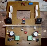
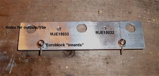
The sprint layout(below 5) fixed "fucup" amp board is done. (below 1) . The driver HS and layout had to take into count the 5 screws (Vbe , drivers , and front outputs. No cap could be in the way , either. Custom driver HS using Euro-terminal "guts" to make it PCB mountable(below 2). The family likes to abuse the "broken" 😀 amp so much they ask me to swap the boards out while they sleep.
Wow .. wow , Classical really "rocks" on this AX ... had to FLAC some new stuff (below 3). I can go right to the rails (240+ W peaks) no issues , even "broken".
Drivers will still be 150/Re (8.5ma) , nikko had 220/Re(6.5mA). Pix 2 heatsink is double area of both nikko HS's combined.
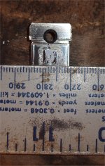
Broke one of the Sanken outputs open (another booboo) , was not a fake (below 4- a 5mm Die). I still have 3 pairs for my triple sub amp , they should do. The ON's are a bigger 6mm+ , that why I am using them for this amp. 🙂
OS
Yeah , no machine shop .. just hand tools , files , hacksaws ... etc. 😀
The sprint layout(below 5) fixed "fucup" amp board is done. (below 1) . The driver HS and layout had to take into count the 5 screws (Vbe , drivers , and front outputs. No cap could be in the way , either. Custom driver HS using Euro-terminal "guts" to make it PCB mountable(below 2). The family likes to abuse the "broken" 😀 amp so much they ask me to swap the boards out while they sleep.
Wow .. wow , Classical really "rocks" on this AX ... had to FLAC some new stuff (below 3). I can go right to the rails (240+ W peaks) no issues , even "broken".
Drivers will still be 150/Re (8.5ma) , nikko had 220/Re(6.5mA). Pix 2 heatsink is double area of both nikko HS's combined.
Broke one of the Sanken outputs open (another booboo) , was not a fake (below 4- a 5mm Die). I still have 3 pairs for my triple sub amp , they should do. The ON's are a bigger 6mm+ , that why I am using them for this amp. 🙂
OS
Attachments
Zoble
Does anyone see a problem with terminating one end of the Zoble network to
either the positive or negative rail ? Hopefully the AC impedance of the rail
would be sufficiently low to allow proper operation.
Does anyone see a problem with terminating one end of the Zoble network to
either the positive or negative rail ? Hopefully the AC impedance of the rail
would be sufficiently low to allow proper operation.
The Zobel is the HF load that the amp prefers to see to help maintain stability.
That HF load cannot and must not include significant inductance or it no longer can easily pass HF.
The output of the amp must go through the Zobel and back into the Power Ground connected to the HF decoupling by as short a route as physically possible.
In the very short term the HF decoupling , as another Member recently reminded us, works as a battery supply for the amplifier.
The output of the amp must go through the Zobel and back into the Power Ground connected to the HF decoupling by as short a route as physically possible.
If the high frequency decoupling is functioning well, wouldn't the rails exhibit a low reactance to ground for suppressing instability. I have some layout space/ routing constraints making it difficult to find a usable power ground.
I am just guessing that the Amplifier output impedance is low enough to prevent noise/ ripple via the Zoble from appearing on the output ?
I am pretty much a beginner with running Spice and would like some suggestions as to simulation of different Zobel configurations.
Thanks
Wouldn't you ask the amplifier to cease amplifying during the entire operational bandwidth of the zobel, and therefore have both effects at a higher pitch than the audio band?
Wouldn't the output impedance be something similar to 0.33R//0.33R//0.33R (on the +) plus trace resistance, and the estimated ESR of a capacitor (0.2R on the -) for an approximated 0.3R output impedance?
To reduce/change noise, a much more effective filter can be calibrated up, up, up to a much higher pitch. This effectively "hides" more of the pitches that were affected by the filter.
The Zobel is the HF load that the amp prefers to see to help maintain stability.
That HF load cannot and must not include significant inductance or it no longer can easily pass HF.
The output of the amp must go through the Zobel and back into the Power Ground connected to the HF decoupling by as short a route as physically possible.
In the very short term the HF decoupling , as another Member recently reminded us, works as a battery supply for the amplifier.
Just as a example of Andrew's statement AND a lot of hair pulling with my Nikko thermal problem ... I will show ideal decoupling / zobel / dual ground returns. (below 1). here I am doing it with 2 complete amps (2 -G1's - dirty earth / 2 G2's - clean earth). The local decoupling can be just 2 10-22uF derated high quality caps if the main rails are short and hefty. 🙂
Below:
A= Flyback diode protection - these DO shunt to the rails. 😀
B= HV supply failure protect - 2 diodes will feed the voltage stage from the main rails in the event of HV shutdown.
C= are the zobel's - fed right to the main speaker/HF "dirty" ground.
D= the 10-22uF local decoupling - each cap must go to the correct amp's G1.
AND there is the separate "G1/G2" grounding scheme.
This amp is down below 125db noise right now - with THIS exact scheme .... it really works. BTW , all 4 G1/G2's go back to a main star. The power rails of both channels are separate and starred back to a "star rail". The other 2 main star connections are from the 68-0-68V supply star and the chassis. Trafo CT goes right to the middle of the main star.
Final schema of the "Big Board" (below 2) A lot of parts on that board. 😀
PS - DWB .... this zobel (10R/.1uF) starts to really attenuate at 800k+ (leaves the audio band alone). 🙂 As far as coupling the Zobel to a rail , consider what would happen during real oscillation ????
OS
Attachments
. . .this zobel (10R/.1uF) starts to really attenuate at 800k+ (leaves the audio band alone). 🙂. . .
Does it calculate like this?
100% 800k
50% Half of 800
25% Half of 400
12% Half of 200
6% Half of 100
3% Half of 50
1.5% Half of 25 which is about 12k.
So, the zobel is 1.5% effective, at 12k, during the audio band?
Or is the filter twice that steep (about 0.12% effect at 12k)?
questions and answers ?? (HMC)
Rod elliot discusses the effect of the standard 10R/100nF zoble about half way down this page : Elliott Sound Products - Audio Power Amplifier Design Guidelines
About .2db down at 20k and .03db down at low frequencies.
I have come to another realization about TMC and my EF2. version 2 of the nikko does not sound quite as good as version 1. The reason (which I fixed) , goes against conventional reason.
According to Cherry (inventor of TMC) , his amps had the additional "30-50" pF cap between driver base and collector .... shunt compensation. If you look at the linked post below at the bottom , Cherry has come to the same conclusions as I have independantly (I missed that post below)
http://www.diyaudio.com/forums/solid-state/171159-bob-cordells-power-amplifier-book-18.html#post2392376
For some reason without the 47pF's a bit of "magic" is gone from the sound. this must be a very low level oscillation from the driver pair. My 2 new boards... one for the forum and one for me( Below 1 and 2) , along with the complete schematic (below 3) will soon be done and fully documented. The driver issue , turn-on thump, and 2ma thermal stability (any temperature) has been incorporated in the circuit. On this amp , I have taken everything into account - even "psychoacoustics". Cherry's "driver stopper capacitors" do add to the final "flawless" results. It is funny I actually heard this minor issue before rebrowsing the Cordell thread. 😕
OS
Attachments
Last edited:
I am sure that's the reason, the 47p caps. helps to eliminate low level HF oscillations riding the signal (that's why is important to have a 100MHZ scope on hand ...), mje340/350 are prone to produce such oscillations by it's own .......
For some reason without the 47pF's a bit of "magic" is gone from the sound. this must be a very low level oscillation from the driver pair. My 2 new boards... one for the forum and one for me( Below 1 and 2) , along with the complete schematic (below 3) will soon be done and fully documented ...
OS
Cheers
Arturo
Cherry spoke of the BD139/140 pair. He said they oscillate at 100mhz if driven with over 10cm trace length. He recommended shorter traces and the stopper caps placed within 1cm of the driver C-B. I adhered to this with the above boards for both resistors and caps(and trace length -40-80mm). My modular design forces me to have 4-8cm between VAS OP and Vbe/driver. The Nikko and my JVC BOTH have the 22-47pf caps from B-C on the drivers and long VAS to driver/Vbe traces.
In the post above the addition of the caps prompted the suggestion of "HMC" "hybrid miller comp" . All I know is that it DOES work , even my ears tell me that.
OS
In the post above the addition of the caps prompted the suggestion of "HMC" "hybrid miller comp" . All I know is that it DOES work , even my ears tell me that.
OS
Last edited:
Secret Zobels
I thought that the series Base resistors on the Driver and Output devices were supposed to take care of any Cranky emitter follower oscillation due to inadvertent negative impedances ?
Just for backup I was considering optional RC's C to B in just the output devices as discussed by Cordell ?
I thought that the series Base resistors on the Driver and Output devices were supposed to take care of any Cranky emitter follower oscillation due to inadvertent negative impedances ?
Just for backup I was considering optional RC's C to B in just the output devices as discussed by Cordell ?
Cherry spoke of the BD139/140 pair. He said they oscillate at 100mhz if driven with over 10cm trace length. He recommended shorter traces and the stopper caps placed within 1cm of the driver C-B. I adhered to this with the above boards for both resistors and caps(and trace length -40-80mm). My modular design forces me to have 4-8cm between VAS OP and Vbe/driver. The Nikko and my JVC BOTH have the 22-47pf caps from B-C on the drivers and long VAS to driver/Vbe traces.
In the post above the addition of the caps prompted the suggestion of "HMC" "hybrid miller comp" . All I know is that it DOES work , even my ears tell me that.
OS
To put a capacitor between drivers base and collector(+ or - power supply) is electrically the same as put it between base and a ground(shunt compensation?). It is not Miller compensation.
dado
To put a capacitor between drivers base and collector(+ or - power supply) is electrically the same as put it between base and a ground(shunt compensation?). It is not Miller compensation.
dado
I didn't say it (that it was miller comp.) This was said on the Cordell book thread. 😛
OS
To put a capacitor between drivers base and collector(+ or - power supply) is electrically the same as put it between base and a ground(shunt compensation?). It is not Miller compensation.
dado
Hi Dado
Semantics ... even if the collector if fixed there is also a parametric "Miller cap." between B-C (with less "capacitance swing" than a loaded collector, but it swings), so the shunt cap. helps linearising this capacitance, and acts also as a LPF (R-C) R=Vas output impedance, it can be a "Miller-Shunt" if you want.
Cheers
Arturo
NEW stuff !! LX (luxman revisited)
After drooling over $30,000 luxman "space amps" , I decided to redo my already tested LX voltage board (below 1) and do the "correct" setup and pair it with a triple. I need a sub amp badly.
Not any triple ... but B. cordell's "DBT" (diamond buffer triple - below 2). He has it as just a concept in his book , but after rereading my "trouble with triples" thread , it decided to go ahead with the simulation/CAD work. This OP stage just has to compensate one Vbe , will be driven by a hefty output pair
( the drivers = njw0281/0302) , and basically be a scalable "mini arc welder".
I almost have the "DBT" layout done , once I do ... it will exist in the real world. 😎 The LX/DBT combo simulates very nicely (attached) ... in fact , the best non-tmc THD-transient performance I have seen. The PCB will have the cap multipliers , PMA's CFP bias spreader , single or dual voltage (without jumpering) capability.
All these subcircuits have been thoroughly tested both for being "idiotproof" and maximum fidelity. The whole package will be a choice of the AX,EX, or LX. The power boards will be the PB120F (EF2 - simple) and the PB150 (this DBT triple). with the triple scalability , i can just make the board longer , clone OP pairs and make a 10 device 80V rail monster that will not "droop" (or drive 2R loads). 😱
WAIT till you see these !!! 😎😎 No more BS- the performance will be superior.
PS - I won't compromise and use angle mounted PCB's ... WHY ??? The pb150 driving a 4R sub with 3-5 pair NJW21193/4's needs excellent thermal conduction (direct mounting) to have the best MTBF. One could use 2 angles to adapt my board , but what is so hard about drilling 7 holes and using self tapping screws ??? (example board- below 3 ... "DBT" / 3-pair OP)
If this works well for my sub , I WILL buy a new $160 par-metal amp case , put the nikko out to the barn and have yet another amp.
OS
Attachments
Last edited:
No , but I did now (below) . What is wrong ?? Gain Xover at 375khz w/ 87 degree margin. I did cap. load with squarewave , minimal ringing. Triple is very stable.
I already built the LX and ran it for 4 months , so I know it has no "bugs", besides having a high impedance VAS (needs a triple to really perform).
OS
I already built the LX and ran it for 4 months , so I know it has no "bugs", besides having a high impedance VAS (needs a triple to really perform).
OS
Attachments
Hi OS, you are correct. Actually I took -20dB as 0 dB so in this respect it looks OK, but 25dB of OLG at 20kHz is it not that to low?
dado
dado
It seems that the PA driver arrangement leads to a reduced VAS load and then a reduced distorsion. Thus a lower OLG may be needed to have similar DHT....but 25dB of OLG at 20kHz is it not that to low?
DHT is 0.002849% for 20V peak 20kHz. Quite good for no TMC.
Sure, we are waiting for the TMC version with increased OLG from OS... 😀
- Home
- Amplifiers
- Solid State
- The MONGREL (supersym II)