Hi all.
Well i thought it was time to do some new stuff. 🙂
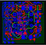
So my first attempt is to make an opamp replacement with jfet inputs.
I will try to hit the 700x700mil size for this one.
This will be fun.
The jfet has an input noise level of 6nV so it will be able to be used for riaa as well as linelevel.
I have attached the diagram. I expect to have the board ready by tomorrow.
Well i thought it was time to do some new stuff. 🙂
So my first attempt is to make an opamp replacement with jfet inputs.
I will try to hit the 700x700mil size for this one.
This will be fun.
The jfet has an input noise level of 6nV so it will be able to be used for riaa as well as linelevel.
I have attached the diagram. I expect to have the board ready by tomorrow.
Attachments
Hi Sonnya,
Nice circuit.
Question . Does cascoding the folded cascode help much? I would think it's use in this application would be minimal but I could be wrong.
I like the use of the Wilson Mirror which I believe is far better than the Widlar that is often used.
Keep up the good work.
Regards,
Jam
Nice circuit.
Question . Does cascoding the folded cascode help much? I would think it's use in this application would be minimal but I could be wrong.
I like the use of the Wilson Mirror which I believe is far better than the Widlar that is often used.
Keep up the good work.
Regards,
Jam
Last edited:
Hi Jam.
Thanks for the comment.
The widlar currentsource is made for the silicon process as it is not possible to make high ohm resistors in the silicon. By adding the resistor in "mirror" transistor it is possible to compensate for it. Correct me if i am wrong.
I can see that i maybee has been "blinded" by the use of folded cascode as i have used them before.
I would be easy to replace it by two wilson mirror and it would require the same or less transistor. It would actually raise the impedance in the tranconductance stage, like i wanted it to.
So i will change that part. thanks for the guiding question.
Sonnya,
Actually I like the four transistor Wilson Mirror (Still might be a bit of overkill).
I will not disagree with you that the folded cascode can sound very good and only requires matching of the diff and current mirror offers equal pull-up and pull-down. All in all a very elegant circuit.
Actually I like the four transistor Wilson Mirror (Still might be a bit of overkill).
I will not disagree with you that the folded cascode can sound very good and only requires matching of the diff and current mirror offers equal pull-up and pull-down. All in all a very elegant circuit.
Attachments
Last edited:
Yes i know it, but i think i will not be able to get it down onto 700x700mil board. It is already a plenty booked board.
Sonnya, if you are making boards I would like to purchase a few if possible......so would a few other members, I bet.
Regards.
Jam
Regards.
Jam
Sonnya, have you simmed it to see what the performance is like? Looks like a an interesting circuit.
indeed ...
mlloyd1
mlloyd1
Sonnya, if you are making boards I would like to purchase a few if possible ...... so would a few other members, I bet.
Regards.
Jam
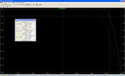
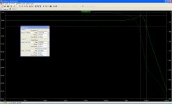
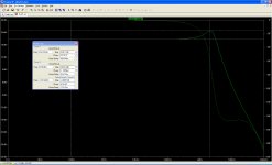
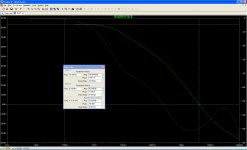
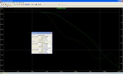
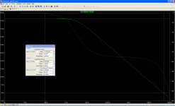
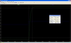
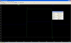
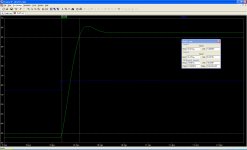
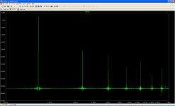
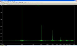
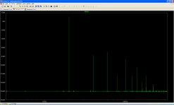
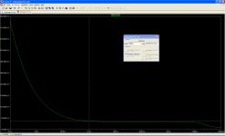
jfet opamp module simulation data
Hi all.
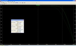
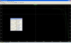
I have attached the simulation data.
Hi all.
I have attached the simulation data.
Attachments
-
 101xgain.jpg247.3 KB · Views: 665
 -
 11xgain.jpg238.3 KB · Views: 725
 -
 2xgain.jpg245.8 KB · Views: 751
 -
 CLGx1+100pFComp.jpg237.2 KB · Views: 502
 -
 CLGx1+100pFComp+220pF.jpg247.5 KB · Views: 459
 -
 CLGx11+1nF.jpg251 KB · Views: 126
 -
 CLGx11+47pFComp+220pF.jpg253.4 KB · Views: 123
 -
 OLG+1nF.jpg257.6 KB · Views: 150
 -
 OLG+470pF.jpg257.3 KB · Views: 136
 -
 OLG+220pF.jpg253.1 KB · Views: 134
The sim data should speech for them self.
The supply voltage is +/-15V
When compensation is added it is added from "COMP" to V-.
Source:50Ohm.
Feedback for x11:10K+1K
Feedback for x101:10K+100R
Feedback for x1:1K
The picture "CLGx11-47pfcomp-22pF-1vppstep" is a 220pF load and not 22pF
The supply voltage is +/-15V
When compensation is added it is added from "COMP" to V-.
Source:50Ohm.
Feedback for x11:10K+1K
Feedback for x101:10K+100R
Feedback for x1:1K
The picture "CLGx11-47pfcomp-22pF-1vppstep" is a 220pF load and not 22pF
Attachments

Last edited:


How does it sim at 20 KHz..??
Did you get what you asked me about?
There are two versions of it.
The first one, which you refer too with folded cascode and the one with wilson mirror in post 7 (Easier to implement on the small pcb).
I have tried with a LED as D2 as weel for simulation. And there is no difference. But we also have .65V CE drop across U5-A and U5-B. This also works good for current mirrors and hawksford cascode which i use in my CFB amp.
Now i have had time to order pcb and stencils.
They will arrive in week 27.
I will make a motherboard for them to test them.
They will arrive in week 27.
I will make a motherboard for them to test them.
- Status
- Not open for further replies.
- Home
- Source & Line
- Analog Line Level
- Jfet folded cascode with diamond buffer opamp