That would have been a major happening 😀
I meant that you can tune the riaa sound by carefully choosing the ouput and vref parts in the shunt.
I meant that you can tune the riaa sound by carefully choosing the ouput and vref parts in the shunt.
1975 it looks like a real classic🙂
Notes:
Back in the 1970's I became disheartened by audio 'progress', for in spite of them presenting much superior specifications, mainstream transistor amplifiers sounded worse than the tube (valve) designs they were supposed to replace. Ultralinear KT88s made good power amplifiers, but transistor circuitry could be much better for pre-amplifiers. Integrated circuits had also developed well, but these were often thought of as offering a lesser performance when compared to discrete construction.
For those who might wish to 'save' to their computer hard-drive a digital copy of their own vinyl record collection, I have redrawn my 1975 vinyl pre-amplifier circuit. It remains capable of optimising disc playback and offers features still not repeated today.
Many designers opinionate that NFB loop controlled amplifiers are inferior because they degrade the sound, and yet I wonder what it is that these individuals think they actually listen to ? The fact is that most vinyl waveforms and CD pits, as pressed into their own disc collections, have already been mastered through a myriad of NFB loop controlled pre-amplifier and mixer stages - this long before anyone can start listening. Indeed, that Mullard developed TDA1034NB integrated circuit which initially cost me £67 for ten, went on to be used by the hundred within what became a classic series of world famous Neve mixing consoles.
Properly designed NFB loop controlled IC gain stages can set standards for excellence, and thus I separately list five elements embodied within my 'old' pre-amplifier design.
(1) A moving magnet pick-up cartridge is an inductive transducer that must be resistively damped and reactively tuned to optimise reproduction.
Hence I fitted a sub-miniature twin gang 500pF variable and screen earthed twin gang potentiometers directly to the input circuitry
It is only *after* you have actually used these input damping and tuning controls whilst music listening to optimise your own equipment line-up, that you can understand just how much mind distracting spin has been repeated about fractional 'dB' variation with respect to an ideal RIAA characteristic.
Cartridge to pre-amplifier matching has a much more significant effect upon reproduction than does the achievement of perfect RIAA equalisation !!!
(2) Another factor greatly affecting reproduction relates to NFB loop controlled gain stage interactions and terminations.
For example, it is possible to build a moving magnet stage using just one or two gain stages per channel, and they can measure near ideal under steady sinewave examination, but this cannot guarantee that they will actually sound good when coping with highly dynamic music waveforms. NFB loop controlled equalisation stages should be buffered at input as well as output. The input terminal of a stage that is called upon to output current not retaining a linear relationship with voltage at all frequencies, will itself not respond with amplitude linearly if fed at high impedance, and this is especially so with bipolar input circuitry.
(Stage interaction often arises, and this is why some power amplifier plus pre-amplifier combinations can reproduce less cleanly than expected.)
Interconnects are not the only cause of audible degradation, thus a separate additional NFB loop controlled line output driving stage that does not load previous circuitry whilst providing a lower output impedance can further improve rather than degrade the final sound by its own presence.
(3) The components used for upper and lower RIAA equalisation characteristics are better separated, as in this circuit.
Passive (non distorting) 750 ohm (or 2x 1k5 in //) plus 100nF close tolerance components not only perform the RIAA hf cut between stages three and four, but they also reduce higher audio frequency noise and distortion from the earlier stages.
Here the line driver stage is already operating at good input signal level with falling input input impedance as frequency increases, and the resulting improvement in sound reproduction becomes instantly recognisable.
Additionally, the uncompensated series feedback unity gain error seen on some other vinyl pre-amplifier circuits is automatically covered.
(4) The original RIAA characteristic was, *is*, sub-bass weak, with a low frequency roll-off that introduces notable bass phase distortion.
For this reason I extended the low frequency equalisation to 25Hz instead of 50Hz, with a switchable option for 'standard' reproduction.
Do not try to use the extended bass response for loud real-time playback (via a computer is okay) unless you have solid floors or your turntable is brick wall mounted.
The 22uF capacitors then introduce multi-pole passive roll-off below 20Hz to more sharply cut turntable and pressing rumbles.
(5) At high live playback levels the extended bass response can set up feedback via differentially energised room resonances. This was easily remedied by connecting the primary of a subminiature transistor radio output transformer between channels, thereby mono-ing the sub-bass without affecting other stereo reproduction. Thus this pre-amp offered a new method for bass feedback reduction that has minimal impact upon the overall bass reproduction level, yet which allows higher 'pop-party' sound levels in undamped rooms.
Don't just look at this circuit and think 'Yeah ?' or 'Sure ?' and say to yourself 'Look at all those capacitors !'.
This analogue pre-amp is a tested design providing not just both a cleaner and quieter background to the music we are meant to hear, but also an optimisable clarity of reproduction that few are likely to have heard before, or even imagined could ever have become a realisable experience.
Today there are many internally compensated audio integrated circuits to choose from, several offering fet input devices. Remotely power your construction with at least four 470uF or 1mF capacitors per 15V rail, and place it beside the tone arm with no more than two feet of screened interconnect.
Do please let me know how you can get on, and let me know which ICs performed well so that they can be mentioned here for other constructors.
Unfortunately I do not have any photographs of my original construction.
Good Luck .......... Graham.
PS. After the 1980's I became even more disheartened by the next supposedly superior technical improvement - the CD. Those who construct this pre-amp might come to understand the significance of our loss !!!
Attachments
Last edited:
Hey I found the schematics of my own phono preamp circuit on the web. I lost my own drawing it was published in Electuur a hobby electronics magazine. It has sections of 4 transistors parallel it shout reduce the noise of the transistor with √8.
It still looks good to me it had sn ratio of 86dB with a MC catridge it was noise free with open volume.
I think I will upgrade the RIAA with MKP now MKT and play with the powersupply. It is still a nice circuit.

It still looks good to me it had sn ratio of 86dB with a MC catridge it was noise free with open volume.
I think I will upgrade the RIAA with MKP now MKT and play with the powersupply. It is still a nice circuit.
Attachments
Last edited:
It might even be possible to incorporate the Mynard variable C/R and damping.... at least it has no tantalums in
Last edited:
I had the same idea, and a shunt power supply. And remove the MKT's in the network.It might even be possible to incorporate the Mynard variable C/R and damping.... at least it has no tantalums in
Hi,
It is probably worth upgrading the EQ Capacitors to Polystyrene (KS markings), these can still be found.
I think there are some areas for improvement.
C8 is really low in value, I think a larger value would be preferrable.
The output stage could be adjusted to have a diode in series with R10/R11 and the omit R15 and the unmarked 1K8, with R13/18 adjusted to get the right values for operating conditions, this should improve thermal stability. Cascoding the input blocks may help.
Also the input transistors run at really current, so I rather doubt the 86dB SNR you claimed for an MC Cartridge (0.5mV), especially in light of the 270 Ohm tail resistor in the feedback network. For MC the feedback tail resistor should be no greater than 10 Ohm and I suspect different transistors at much higher current are needed.
All that said, the old Supra is a classic design and has aged well.
Ciao T
I think I will upgrade the RIAA with MKP now MKT and play with the powersupply.
It is probably worth upgrading the EQ Capacitors to Polystyrene (KS markings), these can still be found.
It is still a nice circuit.
I think there are some areas for improvement.
C8 is really low in value, I think a larger value would be preferrable.
The output stage could be adjusted to have a diode in series with R10/R11 and the omit R15 and the unmarked 1K8, with R13/18 adjusted to get the right values for operating conditions, this should improve thermal stability. Cascoding the input blocks may help.
Also the input transistors run at really current, so I rather doubt the 86dB SNR you claimed for an MC Cartridge (0.5mV), especially in light of the 270 Ohm tail resistor in the feedback network. For MC the feedback tail resistor should be no greater than 10 Ohm and I suspect different transistors at much higher current are needed.
All that said, the old Supra is a classic design and has aged well.
Ciao T
I agree - this is a nice design, and the topology can be tweaked easily for even better performance.
(I cannot read the schematic detials - which one is C8?)
(I cannot read the schematic detials - which one is C8?)
It is probably worth upgrading the EQ Capacitors to Polystyrene (KS markings), these can still be found.
To tickle the saliva, i'll donate 4 of the 10nF KS buggers.
Hi thorsten I never owned a low output mc. Back in the late eighties I owned a X1 MC. After the second one had a open circuit on the coil I scraped orthofon.Hi,
Also the input transistors run at really current, so I rather doubt the 86dB SNR you claimed for an MC Cartridge (0.5mV), especially in light of the 270 Ohm tail resistor in the feedback network. For MC the feedback tail resistor should be no greater than 10 Ohm and I suspect different transistors at much higher current are needed.
All that said, the old Supra is a classic design and has aged well.
Ciao T
An externally hosted image should be here but it was not working when we last tested it.
Later with the DL160

At was as quit as a cd player. The noise was miles away from the noise level of the record with this amp amp-noise became a non issue. Every non-perfection of the grove is audible so good it is so deep detailed it almost becomes a handicap.
Heb je voor mij vier polypropyleen condensatoren van 10nF Jacco?To tickle the saliva, i'll donate 4 of the 10nF KS buggers.
Kan ik goed gebruiken voor de upgrade.
This was Dutch for I want them badly🙂
click the picture it enlarges .I agree - this is a nice design, and the topology can be tweaked easily for even better performance.
(I cannot read the schematic detials - which one is C8?)
C8 is output capasitor.
I want to raise the 150k to 330 and place a series capacitor with the 270 ohm -100ohm of 47u.
So subbas is stretched down to 20Hz and sound much warmer and increase gain.
polypropyleen 10nF ?
KS is polystyrene, interleaved film and foil, 1%, radial lead box type, low inductance, non-aluminum, other BS.
If you like, i'll throw in 4 KS 3280pF as well (i have multi-K in every value, but no 3n3).
Sponsored by the Phono Liberation Front (PLF), includes a freebie envelope and stamp.
That was English, i think.
Last edited:
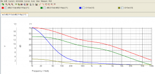
I chanced a few things concerning 50hz correction and amplification factor.
In the simulation the upper opamp has the new configuration, the lower is the original setup.

In the simulation the upper opamp has the new configuration, the lower is the original setup.
Attachments
Last edited:
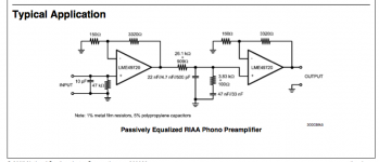
Hi, everyone. I would like to build a fast, simple phono pre using the notes in the LME49720 datasheet. I plan to use batteries for the power supply. My question: When the diagram states 26.1kohm + 909ohm for a single resistor and 22nf/4.7uf/500pf for a single capacitor, what do they mean? Three different caps in parallel for filtering? Two resistors in series for a total of 36.09K? Some better application notes would have been nice. Thanks.
Chosen value is quite good with normal loads. Limit is only a few Hz.C8 is really low in value, I think a larger value would be preferrable.
Hi, everyone. I would like to build a fast, simple phono pre using the notes in the LME49720 datasheet. I plan to use batteries for the power supply. My question: When the diagram states 26.1kohm + 909ohm for a single resistor and 22nf/4.7uf/500pf for a single capacitor, what do they mean? Three different caps in parallel for filtering? Two resistors in series for a total of 36.09K? Some better application notes would have been nice. Thanks.
You only have to copy this design.
26.1k+909ohm means series the same as total resistance of 27k.
22nf//4u7//500pf // means parallel is the sam as 22nF+4u7+500pF total capacity 4,7225 uF. The 22nF has to be a 1% one.
3,8k+100 ohm means series total resistance 3,9kOhm
Attachments
Last edited:
Hi, everyone. I would like to build a fast, simple phono pre using the notes in the LME49720 datasheet. I plan to use batteries for the power supply. My question: When the diagram states 26.1kohm + 909ohm for a single resistor and 22nf/4.7uf/500pf for a single capacitor, what do they mean? Three different caps in parallel for filtering? Two resistors in series for a total of 36.09K? Some better application notes would have been nice. Thanks.
You only have to copy this design.
Thank you, Helmuth. I see my math is suspect (no surprise.) That is the diagram from which I an working. It is for a shop sound system, so no need for absolute fidelity in the the less than ideal listening space.
Thank you, Helmuth. I see my math is suspect (no surprise.) That is the diagram from which I an working. It is for a shop sound system, so no need for absolute fidelity in the the less than ideal listening space.
But it will be absolute fidelity with battery power-supply I would ad 100uF capacitors for fast current peaks.
- Status
- Not open for further replies.
- Home
- Source & Line
- Analogue Source
- Which DIY phono-stage gives great results?