I have had a few email exchanges with Keatoken. He said he is very busy at the moment so I think I may post a couple of messages in our exchanges for him for the benefit of others.
Keantoken:
Let me show you the datasheet. VceSat is the parameter we're looking for, in figure 4.
http://www.fairchildsemi.com/ds/BC/BC550.pdf
I like to keep Vcb positive. Transistors are most linear with at least 2V Vce. You can see this in figure 1. Keeping base current the same, Vce is varied in order to observe Early effect (change in transistor parameters with Vce). Between 20 and 10mA, you can see that 1V Vce or more is desirable (the line begins to straighten out at that point). VceSat is the point where Early effect begins to destroy transistor operation, when Vce is too low. If it matters enough, you can get away with just 70mV Vce at 20mA. But at this point, as you can see again in figure 4, Early effect will reduce that transistor's natural resistance to input voltage variation (decreasing PSRR).
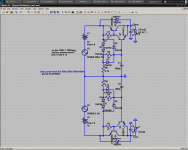
The problem so far with the diodes is that the bias current through them is on the order of uA. For this reason their voltage drop will be below what it is at currents in the mA. I think adding one more resistor may be beneficial to the circuit, but it could just as well be useless. See attached schematic. I give the diodes 5mA bias. This should increase Vce a little, and make it a little more predictable. You could also use a red LED here, for default 1V Vce (may improve PSRR) (2.6V voltage drop), and less noise than a 4 diode string.
For the 2SC5171, it is advisable to have a heatsink. Even though the device specified for an operating temperature up to 150C, if you look at the Hfe chart, operating at higher temperatures reduces the Hfe range. At 300mA you are just at the rolloff point, and this may differ between devices. Even if this is not a concern, the device may get hot enough to melt nearby components and damage the PCB (and transferring heat to other components through the leads).
39R should work, but I wouldn't go any higher.
- keantoken
Keantoken:
Let me show you the datasheet. VceSat is the parameter we're looking for, in figure 4.
http://www.fairchildsemi.com/ds/BC/BC550.pdf
I like to keep Vcb positive. Transistors are most linear with at least 2V Vce. You can see this in figure 1. Keeping base current the same, Vce is varied in order to observe Early effect (change in transistor parameters with Vce). Between 20 and 10mA, you can see that 1V Vce or more is desirable (the line begins to straighten out at that point). VceSat is the point where Early effect begins to destroy transistor operation, when Vce is too low. If it matters enough, you can get away with just 70mV Vce at 20mA. But at this point, as you can see again in figure 4, Early effect will reduce that transistor's natural resistance to input voltage variation (decreasing PSRR).
The problem so far with the diodes is that the bias current through them is on the order of uA. For this reason their voltage drop will be below what it is at currents in the mA. I think adding one more resistor may be beneficial to the circuit, but it could just as well be useless. See attached schematic. I give the diodes 5mA bias. This should increase Vce a little, and make it a little more predictable. You could also use a red LED here, for default 1V Vce (may improve PSRR) (2.6V voltage drop), and less noise than a 4 diode string.
For the 2SC5171, it is advisable to have a heatsink. Even though the device specified for an operating temperature up to 150C, if you look at the Hfe chart, operating at higher temperatures reduces the Hfe range. At 300mA you are just at the rolloff point, and this may differ between devices. Even if this is not a concern, the device may get hot enough to melt nearby components and damage the PCB (and transferring heat to other components through the leads).
39R should work, but I wouldn't go any higher.
- keantoken
Attachments
Last edited:
I did the change last night by taking out 3 x 1N4148 replacing them with 1 x 3mm red LED, and added a 5k1 resistor.
Vce for the driver was 1.32V, but is now 14.96-13.06=1.90V. Vce for the pass transistor, or the total voltage drop of the K-Multiplier is 15.65-13.06=2.60V.
Output with various voltage drops of the diode string:
1 x 1N4148: about 12mV non sine wave at 14.65VDC. Subjectively It did not sound good.
2 x 1N4148: about 8mV non sine wave (but rounder) at 13.90VDC. Subjectively it sounded better.
3 x 1N4148: about 6mV sine wave (or close) at 13.83VDC. Subjectively it sounds the best.
1 x LED + 5k1: about 3mV sine wave (or close) at 13.06VDC. Subjectively it sounds good but not the best.
The LED version with 2.60V voltage drop does not really work for me because in that case the Marantz reg has been left with only 1.7V for voltage drop, which is insufficient. The Marantz reg sets 11.30V output voltage but with the LED prereg it has only 11.10V at the output, indicating too low input voltage. With 3 x 1N4148, I had 2.52V voltage drop for the Marantz reg and it appeared to be working with the desired 11.30V output voltage.
So for me, 3 x 1N4148 work the best. I will reverse the last change and am content with 3 x 1N4148.
Note that the LED version might be better if you could afford the higher voltage drop.
Last edited:
Thanks HiFi, a lot of knowledge passes in private conversations, much of it worth sharing...
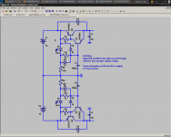
The schematic I sent you contains some possibly misleading features:
1: Output devices are 2SD669A/B649A. These will work to 100mA, but the 2SC5171/A1930 work to 300mA, are just as fast (if not faster) and are easier to get for some people.
2: Drivers are BC547C/557C. The BC550C/560C have slightly better noise specs, not sure if it matters but I prefer to buy the superior part anyways if it's of little consequence to the wallet.
Here is a cleaned up, nice schematic representing the ideas I described to HiFi.
- keantoken
Attachments
You should be able to, as long as you use an appropriately rated capacitor. However I don't think that output impedance will be improved (HF impedance might).
- keantoken
- keantoken
Hey everyone. Many months have passed and I have done many things. I have destroyed my Kmultipliers many times. It is time for an update.
We figured out why HiFi's regulators did not reach spec. He had counterfeit transistors. Now they perform just like my own prototype.
The Kmultipliers only almost reach the 60db isolation point. I think I know why this is. The simulation models lack quasi-saturation modeling, so transistors will perform too good at low Vce. So it seems clear to me the next order of business is to use low-Vcesat transistors. The PEMZ7 transistors from NXP seem ideal for this task; the BC817/807 may also but they do not show low-current Vce behavior. I would certainly appreciate suggestions for transistors that are less exotic.
For the output transistors I want to find a good low-VceSat transistor >1W that has good Hfe until at least 400mA. I suspect the 2SC5171/A1930 are not as good as the datasheet says and I think the MJE243/253 could be an improvement, so I will try them.
With these improvements it may be possible to increase isolation to above 70db.
Furthermore, using a TL431 I may be able to make a voltage regulator version.
The Kmultiplier is still particularly suited to high-voltage filtering, but no one has used it for that yet, and I encourage anyone interested to discuss it with me.
- keantoken
It is time for another update.
I wrote a webpage about the Kmultipliers. It contains updated information and includes what I've learned from more experimentation. I'd appreciate feedback.
http://www.fidelityforce.com/keantoken/content/Kmultiplier.html
I wrote a webpage about the Kmultipliers. It contains updated information and includes what I've learned from more experimentation. I'd appreciate feedback.
http://www.fidelityforce.com/keantoken/content/Kmultiplier.html
It worked for me yesterday.
But it's not connecting today.
I still have the page up. I better save as before I lose it.
Agh....
Save as does not work.
It's trying to go back to source to download again.
But it's not connecting today.
I still have the page up. I better save as before I lose it.
Agh....
Save as does not work.
It's trying to go back to source to download again.
Last edited:
Hello Iko,
Nice page, KMultipliers.
I am using a basic CMx with the IRFP240/9240s and works rather well with my F5 amp, and curious if this cct can be expanded to drive the steady state 1.6A, and peaks of 2.5A - rails are about +/- 25volts?
Nice page, KMultipliers.
I am using a basic CMx with the IRFP240/9240s and works rather well with my F5 amp, and curious if this cct can be expanded to drive the steady state 1.6A, and peaks of 2.5A - rails are about +/- 25volts?
I have got it....Very instructive.... Thank you.
Can it be used before a LM317 to create a superreg?
Can it be used before a LM317 to create a superreg?
I'm not sure why the page wouldn't load, but my friend has a rather special DIY network security system, so maybe it doesn't like you. I will have to speak with him on this. The link is valid, and loads for me.
Using the Kmultiplier before the chipreg is a great way to boost RF input rejection.
The K Multiplier
Using the Kmultiplier before the chipreg is a great way to boost RF input rejection.
The K Multiplier
Thank you.
I have been using a "normal" cap multiplier before the ship to create good 5v regs for my DAC.
Can I use the circuit as per your site schematic for a +5v reg also ?
I have been using a "normal" cap multiplier before the ship to create good 5v regs for my DAC.
Can I use the circuit as per your site schematic for a +5v reg also ?
Hello Iko,
Nice page, KMultipliers.
Not Iko, keantoken!
1.6A steady is getting into wary territory. At this point outputs are generally too slow and Hfe is too low to be unconditionally stable and still have low output impedance. In simulation this is looking like it can work.
The MJE200/210 seem like reasonable transistors in this current range, and while the MJE15033/32 are more robust they are morbidly slow in comparison. Ultimately I would need to test the circuit myself to see if it is viable. You will certainly not get all the performance at 1A that you can get from the standard Kmultipliers at 100mA.
Luckily, both Cordell and Andy_C have provided custom simulation models for the MJE13032/33 pair, so I'm reasonably sure this is the best solution. Again to be sure, I will need to test it myself or have you take some simple measurements.
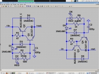
For best performance the diode string needs another diode. It's not necessary but it helps.
It will help to know what is the pk-pk input ripple voltage at the point you are intending to put the Kmultipier.
EDIT: Added schematic.
Attachments
Last edited:
Thank you.
I have been using a "normal" cap multiplier before the ship to create good 5v regs for my DAC.
Can I use the circuit as per your site schematic for a +5v reg also ?
Definitely. It works at any rail voltage, C1 needs to be rated for that voltage.
would a medium power mosFET suit better?...............1.6A steady is getting into wary territory. At this point outputs are generally too slow and Hfe is too low...............
How would the circuit be modified to accommodate a FET pass transistor?
The Kmultiplier NEEDS to have BJTs for high transconductance or it cannot have low Zout, high PSRR, and low voltage drop all at once. It could be modified to use FETs, but then it would not be nearly so useful.
Ah "keantoken", sorry about that.
Those MJ200/210 are 'tuff' little things for sure - I wonder if it would be possible to use 2 in //, and reduce the strain on them without 'current hogging', etc?
Probably better to just reduce the current, I guess to about the usual 1.3A, or less.
The Power Supply is a good quality (Tortech) 600Va torroidal Txr (for both channels) 21v AC, -> byv27 diode bridges -> 4,700uF Siemens B41455 -> 0.1R -> 12,000uF 'Elna for Audio' -> IRFP240/9240 CMx -> 10,000uF SlitFoils.
Dressed this up with Schaffner line filter, CL-60s, basic dc trap, transformer tuning, R-C snubbers, good & short wiring, dc protection/delay, and so on.
Sounds like you've got an advanced passive PSU section.
I thought of paralleling outputs, but the MJE200/210 are still very nonlinear and not working very well at low Vce. The MJE15032/33 on the other hand worked as well as I could hope for up to the max current, with the exception of speed. Of course this is in simulation.
I tried MJE240/250 and there was a surprising reduction in PSRR. So good Vcesat specs for the output transistor are important. And this doesn't simply mean having low Vcesat; it also has to have high Early voltage. In the OnSemi models it is very low. I don't know if they can work well even if paralleled.
Power supply the result of "long time fiddle" and chasing up "good bits" over long time.
The F5 amp is quite sensitive to power supply quality and it's relatively simple to alter the amp's sound via the supply component changes, and a little extra effort - the good quality parts make it easier, except for the size of the final product.
I'm playing around with a simple regulated version (as per Aleph style zener reg) but for all the extra heat and power loss, there isn't that much improvement to the sound, even with all the good caps throughout - a bit disappointing actually. [I may have missed something in the build, perhaps ...] and I'm quite interested to see what your much more sophisticated cct will do in same amp.
It looks like most of these adequate transistors aren't quite suitable for the higher current load - too easy!
I had a weird thought, maybe totally off target - in the F3 amp, there is a little super Jfet (Lu1014) operating with a cascoded power Fet (IRFP240 )- would these items be at all suitable for operations in the Kmx? (I've still got a few left, you see!)
- Home
- Amplifiers
- Power Supplies
- Keantoken's CFP cap multiplier