hi apexaudio
greetings can vas stage of ax14 and a triple darlington output stage
be used for more power with 10 output pairs what would be power output of amp at 80 volt dc rails be is it possible
thanking you
andrew lebon
Yes, you can get over the 500W of output power.
Regards
Hello sir mile
thank you, finally I finished with my AX14, sounds quite satisfactory results. and I have a plan to replace my TDA7294 with AX14.
if I want to make the AX14 as a sub amp is there anything that needs to be changed at the input section , in addition to the existing sub filter?
Regards Chakra 🙂
No need to change anything.
Regards


Hi apex, i want to build AX14 with + - 47V psu. Can i use A992 for Q1 and Q2?
What will be bias setting for +- 47 V and 4 ohm load ? what will be output power ?
kindly reply. THANKS
What will be bias setting for +- 47 V and 4 ohm load ? what will be output power ?
kindly reply. THANKS
hello mr. mile help me, i'm confused with AX14 and AX16. can you send scheme and pcb to my e mail? grand2512@gmail.com thank you, regards
hello mr. mile help me, i'm confused with AX14 and AX16. can you send scheme and pcb to my e mail? grand2512@gmail.com thank you, regards
Overload detect is add on AX16, and send +HV on PRO out...
hi apex,I build AX14 pcb by myself,but don't work.DC +-24,test the output and the gnd is DC +20.4V why?where is wrong?
I come from hifidiy.bbs,
I come from hifidiy.bbs,
Last edited by a moderator:
hi apex,I build AX14 pcb by myself,but don't work.DC +-24,test the output and the gnd is DC +20.4V why?where is wrong?
I come from hifidiy.bbs,
Can you post pictures? Do you connect input GND to PSU GND?


I have connect the gnd with pgnd already.
pgnd isnot the psu gnd,but the power gnd,i havenot build the psu,where wrong?
thanks
pgnd isnot the psu gnd,but the power gnd,i havenot build the psu,where wrong?
thanks
Last edited:

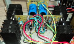
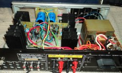
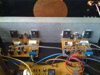
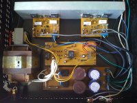
Advice taken, bd139 moved to the heatsink between the power transistors, second module built, case from local electronic supplier, DC detect and delay module added, space for 12 cms fan.
PSU: 200VA trafo with 2 x 39 Vac, 2 x KBPC806 bridge rectifier, 16800uF per side
DC detect and delay from Silicon Chips magazine.
First stereo test: I like it!! 😀 Very clear, no noise without music, good voices and bass, highs ok (on piezo tweeter).
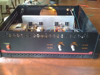
I'm attaching some pictures, I'll add some more pictures with better resolution when I get my camera back.
Mile, I saw my first amp picture on facebook, thanks for putting it there, and thanks again for sharing your design. 😎
PSU: 200VA trafo with 2 x 39 Vac, 2 x KBPC806 bridge rectifier, 16800uF per side
DC detect and delay from Silicon Chips magazine.
First stereo test: I like it!! 😀 Very clear, no noise without music, good voices and bass, highs ok (on piezo tweeter).
I'm attaching some pictures, I'll add some more pictures with better resolution when I get my camera back.
Mile, I saw my first amp picture on facebook, thanks for putting it there, and thanks again for sharing your design. 😎
Attachments
546 instead of 547,556 instead of 557 .is it ok?
It's ok, and amp can work with +/-24V DC, but better use proper rail voltage and post pictures...
Advice taken, bd139 moved to the heatsink between the power transistors, second module built, case from local electronic supplier, DC detect and delay module added, space for 12 cms fan.
PSU: 200VA trafo with 2 x 39 Vac, 2 x KBPC806 bridge rectifier, 16800uF per side
DC detect and delay from Silicon Chips magazine.
First stereo test: I like it!! 😀 Very clear, no noise without music, good voices and bass, highs ok (on piezo tweeter).
I'm attaching some pictures, I'll add some more pictures with better resolution when I get my camera back.
Mile, I saw my first amp picture on facebook, thanks for putting it there, and thanks again for sharing your design. 😎
Nice work, is this diy case or you use some from brand amp?
- Home
- Amplifiers
- Solid State
- 100W Ultimate Fidelity Amplifier