Hi Guys,
But I modified the existing picture with polarities of the caps, see attached!
The pic with the bridge will follow soon.
As long as the blue wires on the six caps on the left link together all the six cap's NEGATIVE terminals (and).....
....the blue wires on the six caps on the right link together all the six cap's POSITIVE terminals.....
.....the the cap bank wiring looks OK.
A quick check........ without the rectifiers (or any other connections) attached to the cap banks, discharge the negative cap bank with a low-value resistor across the rectifier + and - inputs on your cap bank (this should insure your caps are discharged). Then place a DMM across these two rectifier inputs on your cap bank. Initial resistance should be low, but should climb over time (this would test to make certain you do not have any major shorts in your cap banks).
Do the same for your other cap bank.......
discharge the negative cap bank with a low-value resistor across the rectifier + and - inputs on your cap bank (this should insure your caps are discharged). .
just came to my mind that even if one doesn't want bleeders, it seems like a good idea to at least have them mounted during assembling, and for test runs
and if you dont like bleeders, just remove them once everything is running fine
Tinitus..... totally true..... and that's why, during construction (particularly of HV stuff like transmitters and vacuum tube amps), I also use the "shorting wand" approach...... a resistor, with one lead hooked to ground, and the other lead hooked to a test probe. Comes in handy, to discharge other caps during testing......
P.S. Don't know why someone would consider buidling a hefty power supply, without bleeder resistors. That's kinda like building a fast sportscar, without a good brake. Safety, ya know.......
P.S. Don't know why someone would consider buidling a hefty power supply, without bleeder resistors. That's kinda like building a fast sportscar, without a good brake. Safety, ya know.......
'N as long as we are discussing shorting probes - why not DIY one. After all - this is DIY!
Using Energy Rated Resistors for High Voltage Capacitor Discharging
Not quite the same thing as the 3ft. (1meter) jobs I used for 100 Kvolts - buuuut for audio it should get you close enough. 😀😀😀
Hey CanAm Man - having any after effects from drinking last weeks vintage vino outta da cans? 😱
Using Energy Rated Resistors for High Voltage Capacitor Discharging
Not quite the same thing as the 3ft. (1meter) jobs I used for 100 Kvolts - buuuut for audio it should get you close enough. 😀😀😀
Hey CanAm Man - having any after effects from drinking last weeks vintage vino outta da cans? 😱
I'm fearless and dumb Papamps builder !
I don't need da stinkin' bleeders!
( I'm using shunt regs everywhere , so I'm used to bleed ) , but not here ......
I don't need da stinkin' bleeders!
( I'm using shunt regs everywhere , so I'm used to bleed
) , but not here ......"Question - do you need a insulating shoulder washer for the hole of a TO-247? Or can you just but a bolt straight through? Obviously you need a silpad or mica on the bottom of the case..."
i know i'm late, but are the cases of the transistors conductive? and thats why you need insulators?
i know i'm late, but are the cases of the transistors conductive? and thats why you need insulators?
I'm fearless and dumb Papamps builder !
I don't need da stinkin' bleeders!
( I'm using shunt regs everywhere , so I'm used to bleed
Hey CanAm Man - having any after effects from drinking last weeks vintage vino outta da cans? 😱
Gees---energy rated resistors..... I haven't heard that term, in a while!
Yeah....bad reaction from that Chardonnay in cans. After a six pack, when I sit in a swivel office chair, my feet want to point to the North pole.... I'm guessing I'm just outgassing (or would it be "degaussing"...?) the metal from the cans..... 😱
"Question - do you need a insulating shoulder washer for the hole of a TO-247? Or can you just but a bolt straight through? Obviously you need a silpad or mica on the bottom of the case..."
i know i'm late, but are the cases of the transistors conductive? and thats why you need insulators?
Nope. The (black) plastic case of the MOSFET is not conductive (and you can prove that to yourself with an ohmmeter). You can use a machine screw to fasten the MOSFET, but you should also use a large fender washer or large wave washer to spread the bolting torque load over a large portion of the MOSFET's plastic face. See pic, attached.
Yep...... in most cases, the metal tab of the MOSFET MUST be isolated from the metal chassis/heatsink. And yes, to do that with a thermally conductive, but electically non-conductive means (mica and goop, silpad, chunky-style peanut butter).
(OK....forget about peanut butter--the jury is stll out, on that one....!)
I'm fearless and dumb Papamps builder !
I don't need da stinkin' bleeders!
I can see the bumper stickers now:
BLEEDERS: USE THEM.....OR BECOME ONE....!
Nope. The (black) plastic case of the MOSFET is not conductive (and you can prove that to yourself with an ohmmeter). You can use a machine screw to fasten the MOSFET, but you should also use a large fender washer or large wave washer to spread the bolting torque load over a large portion of the MOSFET's plastic face. See pic, attached.
Yep...... in most cases, the metal tab of the MOSFET MUST be isolated from the metal chassis/heatsink. And yes, to do that with a thermally conductive, but electically non-conductive means (mica and goop, silpad, chunky-style peanut butter).
(OK....forget about peanut butter--the jury is stll out, on that one....!)
Perfet, thank you for sharing your knowledge!
PSU ready
Hi,
finally I've got everything I need to setup the PSU.
Please see attached the pictures. I haven't started it yet, 1st want to check with you guys. Someone needs to give me a sign off 😉
Of course the amp is not yet on the pictures but will follow soon. I also changed the polarity of the caps in the 1st row, it's now +--+ -++-
Thanks in advance!
Cheers,
Mallard
you need some insulator beneath mains contacts on that contact blocks
shorten those noninsulated ends
shorten those noninsulated ends
I need more information to help,
Is this transformer a single Primary?
Is the Primary the tan leads?
Where is the mains fuse?
Do you have a chassis earth?
Verify that the mains lead is color-coded thus;
Blue (hot)
Brown (neutral)
Green (earth)
Does the transformer have it's own earth lead? The green that originated near the secondaries and is currently not hooked up to anything?
Something looks wrong (to my eye) about your mains connection/thermistors/primary but I am not sure exactly what without more information.
Last edited:
I need more information to help,
Is this transformer a single Primary?
Is the Primary the tan leads?
Where is the mains fuse?
Do you have a chassis earth?
Verify that the mains lead is color-coded thus;
Blue (hot)
Brown (neutral)
Green (earth)
Does the transformer have it's own earth lead? The green that originated near the secondaries and is currently not hooked up to anything?
Something looks wrong (to my eye) about your mains connection/thermistors/primary but I am not sure exactly what without more information.
1. It's a single primary with 600VA driving left and right side channels
2. The 2 tan leads are the primary
3. The main fuse not on the picture, it's integrated in the power plug to the chassis
4. Yes chassis earth the green/yellow lead
5. Yes the transformer has it's own earth lead and it's unfortunatly not connected on the picture but I will connect it to the green/yellow chassis ground.
6. I implemented 2 Thermistors, one on the primary side and one on to the chassis ground.
Still confused?
The thermistor on the primary needs to be attached to the hot mains lead.
The Ground from the mains lead needs to be attached directly to the chassis.
The PSU ground (your copper buss bar) attaches to the chassis ground with the other thermistor in series - like this:
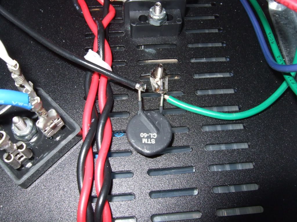
In this photo the black wire attaches to the chassis through the thermistor, and the green wire is the mains earth. Remember to scrape to bare metal and use a star washer.
Once that is done, disconnect the leads from the rectifiers to the capacitors and plug it in. Make sure your DC polarity is correct with a DVM.
The Ground from the mains lead needs to be attached directly to the chassis.
The PSU ground (your copper buss bar) attaches to the chassis ground with the other thermistor in series - like this:
In this photo the black wire attaches to the chassis through the thermistor, and the green wire is the mains earth. Remember to scrape to bare metal and use a star washer.
Once that is done, disconnect the leads from the rectifiers to the capacitors and plug it in. Make sure your DC polarity is correct with a DVM.
I also changed the polarity of the caps in the 1st row, it's now +--+ -++-
So....it was the polarity of the caps, huh? (See my post, #808....)
A matte black chassis..... I like that.....!! LOL.............
Last edited:
Hi,
finally I've got everything I need to setup the PSU.
Please see attached the pictures. I haven't started it yet, 1st want to check with you guys. Someone needs to give me a sign off 😉
Of course the amp is not yet on the pictures but will follow soon. I also changed the polarity of the caps in the 1st row, it's now +--+ -++-
Thanks in advance!
Cheers,
Mallard
Make sure the copper plates are insulation covered from accidental drop of simple tools like a screw driver - it can short the raw power supply
no open Mains voltage
such precautions will help prevent costly accidents
kannan
Verify that the mains lead is color-coded thus;
Blue (hot)
Brown (neutral)
Green (earth)
The correct colour code is
Brown (hot)
Blue (neutral)
Green/Yellow (earth)
It won't make any difference to the transformer, but you don't want to end up with the fuse in the neutral line, that could be dangerous in a 'blown fuse' fault condition.
- Home
- Amplifiers
- Pass Labs
- How to build the F5