I finally got most of my bottom panel drilled out. I've just got to find a spot for chassis ground.
How far back in this thread for the terminal block/ thermistors (cl-60)?

How far back in this thread for the terminal block/ thermistors (cl-60)?

Member
Joined 2002
I finally got most of my bottom panel drilled out. I've just got to find a spot for chassis ground.
How far back in this thread for the terminal block/ thermistors (cl-60)?
what chassis did you end up going with ?
Member
Joined 2002
It looks like a 4U by 400mm Pesante Dissipante from Modushop.
I'm just saving some money, have new job, going to be ordering 2 new chassis for my aleph minis.
These chassis :
An externally hosted image should be here but it was not working when we last tested it.
BUT in black 🙂
Something's wrong
Hi,
I finally powered up the 1st channel. Hmm... no smoke, the light bulb
in the hot line turns on and fades out but the LED on the amp pcb fades out as well. 😕
Actually the LED should be always on but it's not. PSU voltage is fine @ 24.4V
When I turn off the amp (discharge the caps) and fire it up again the LED is not on at all, even not for a second.
I turned P1 / P2 down to zero just before firing it up the 1st time. When I now start to turn on P1 I get at max 0.02V over R11. So something is happening but not quite properly. The heatsink doesn't get warm at all...😕
Is the LED damaged and shorts now V+ to gnd? Will check this tomorrow...
Any suggestion?
In your case, that likely means you don't know what happened to your prescription glasses after you hit the bottle again last night. 
ZM..... I have a friend with a crystal ball. The doctor says he'll still be able to have children, though........
hmmm...
Yeah...I know the lough is always on the loser 😡
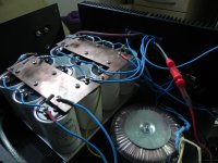
But on the pictures attached there is imo nothing to discover but please feel free!
I've asked the question because it could be the case that somebody experienced similar behaviour and could probably give me some hints. I mean what is a max volatge of 0.02V across R11 indicating. Obviously Q3 is not raming up very well. 😕
Who can help to localize or to isolate the error on y pcb?
Thanks in advance !!!!!
Cheers,
Mallard
Yeah...I know the lough is always on the loser 😡
But on the pictures attached there is imo nothing to discover but please feel free!
I've asked the question because it could be the case that somebody experienced similar behaviour and could probably give me some hints. I mean what is a max volatge of 0.02V across R11 indicating. Obviously Q3 is not raming up very well. 😕
Who can help to localize or to isolate the error on y pcb?
Thanks in advance !!!!!
Cheers,
Mallard
Attachments
Q : The copper plate at the power supply is treated or is it bare metal ?
It's bare copper/metal.
Better to solder some tin around the mounting hole area, both sides.
(bare copper and sulphur in the air are not a happy couple)
(bare copper and sulphur in the air are not a happy couple)
Playing Mr. Obvious here for a minute, but you don't actually state that you took out the light bulb TESTER....?Hi,
I finally powered up the 1st channel. Hmm... no smoke, the light bulb
in the hot line turns on and fades out but the LED on the amp pcb fades out as well. 😕
Actually the LED should be always on but it's not. PSU voltage is fine @ 24.4V
When I turn off the amp (discharge the caps) and fire it up again the LED is not on at all, even not for a second.
I turned P1 / P2 down to zero just before firing it up the 1st time. When I now start to turn on P1 I get at max 0.02V over R11. So something is happening but not quite properly. The heatsink doesn't get warm at all...😕
Is the LED damaged and shorts now V+ to gnd? Will check this tomorrow...
Any suggestion?
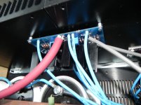
Also, how can you NOT create mass-confusion with all the same color wires? Help yourself out a little....
Last edited:
I've done it with an without the light bulb with the same result.
+- 24.4V coming out of my PSU and into the amp in both ways.
I know, all the cable with the same color is bit difficult to handle but I'm
100% sure there is no cabling error.
+- 24.4V coming out of my PSU and into the amp in both ways.
I know, all the cable with the same color is bit difficult to handle but I'm
100% sure there is no cabling error.
speaker binding posts
hmm, I've got a set and trying to make a nice connection, but I guess my 30 watt iron is doing a poor job getting the binding hot enough for the solder to flow.
I end up with a cold joint and a blob of solder on my wire. Maybe I should use 2 irons, lol.
Is there a trick to these posts?
hmm, I've got a set and trying to make a nice connection, but I guess my 30 watt iron is doing a poor job getting the binding hot enough for the solder to flow.
I end up with a cold joint and a blob of solder on my wire. Maybe I should use 2 irons, lol.
Is there a trick to these posts?
- Home
- Amplifiers
- Pass Labs
- How to build the F5