I really thank you, by the kindness, dear Tinitus, to let the subject
be sucked into the black holes of the Universe..i want all that dirty thing to be attracted and swalow by the anti materia.... that a strong gravitation force atracts all the evil and keep those things distant from our constellation.
One day we gonna have Nico back to find a decent solution for this issue.... i hope he is alive and will return... despite i am afraid he may have passed away... i have hope he is just giving a break or healing from bad moments.
regards,
Carlos
Sure thing
Only positive things makes sense 😉
But troubles are part of it too, no free lunch, as they say
Whatever we wants, its hard work
Well, my life is too short for such things
Shouldnt we be talking about amps?
Maybe we handle that better😀
Only positive things makes sense 😉
But troubles are part of it too, no free lunch, as they say
Whatever we wants, its hard work
Well, my life is too short for such things
Shouldnt we be talking about amps?
Maybe we handle that better😀

Thank you...all thread alive once again
Dx Ressurrection!
regards,
Carlos
Dx Ressurrection!
regards,
Carlos
An externally hosted image should be here but it was not working when we last tested it.

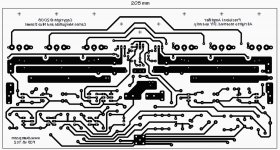
Dx Precision 1 - the schematic
I have all those images in pdf, also i have a pdf package with all gerbers from Precision 1 and also HRII.
Needing those files, then write to:
panzertoo@yahoo.com
And i will be glad to upload them to you.
regards,
Carlos
I have all those images in pdf, also i have a pdf package with all gerbers from Precision 1 and also HRII.
Needing those files, then write to:
panzertoo@yahoo.com
And i will be glad to upload them to you.
regards,
Carlos
Attachments

Dx Precision is reliable, looks good and sounds good too
I am searching for a better image to post.
For a while, you that is new in our forum, take a good look at the nice work done by Nordic with the pcboard.
Was a very hard work fellows.... result good because we sweat to create, to evolute, to adjust and to test it.
We had, in the past, a group buy and several stereo kits were sold at cost price.
We have no more boards...you have to order using Eagle files i can provide, or to etch at your home using the board layout already provided (I have pdf if needed)
regards,
Carlos
Attachments

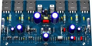
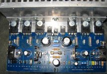
This is the Precision 1.... lovely board made by Nordic
the family name is Nico Daneel, from South Africa... a good friend missed.
The Precision 1 is a high quality audio amplifier, with astonishingly good sound reproduction having huge bass and lovely midranges... treble is just fair and normal.
regards,
Carlos
the family name is Nico Daneel, from South Africa... a good friend missed.
The Precision 1 is a high quality audio amplifier, with astonishingly good sound reproduction having huge bass and lovely midranges... treble is just fair and normal.
regards,
Carlos
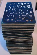
Here you have the gerbers for the Precision 1... this way will be easy
to order boards from factories.
Enjoy, it is a nice and powerfull audio amplifier....Nico Daneel have ordered 50 boards and distributed all over the world.... seem almost everybody have received, naturally the ones have ordered in the group buy made.
AndrewT informed that have not received..... i had not the information he had ordered boards from Nordic.
attached the Gerber files.... it is a DIY amplifier, to share wide world, it is not to sell having profit.... and to pay Nico's part will be difficult, i have strong suspections he has passed away, because he was an audio fanatic and a computer fanatic..not chance for him to abandon our forum the way was done.
regards,
Carlos
Attachments
I am calling this thread back because we have one South American building
Interesting...so long time has passed and i have one more builder.
regards,
Carlos
Interesting...so long time has passed and i have one more builder.
regards,
Carlos
You should have studied this amp more deeply
as it s potentially superior to your dx and blame es
if correctly designed and implented..
as it s potentially superior to your dx and blame es
if correctly designed and implented..
This amplifier had the help from Nordic (Nico Daneel) from South Africa
I miss a lot Nico....a great helping hand....full of enthusiasm.
He disappeared...i do think he passed away
regards,
Carlos
I miss a lot Nico....a great helping hand....full of enthusiasm.
He disappeared...i do think he passed away
regards,
Carlos
Attachments
Last edited:
need help with voltage readings
Sir Carlos,
Good Day to you Sir,
I have build a prototype of your dx precision 1 and on my initial testing i had this values:
2sa1943:B=.312V, C=64.1V, E=.841V
2sc5200:B=.223V, C=63.3V, E=.225V
BD139:B=.810V, C=.829V, E=1.448V
2sa1837:B=1.439V,C=63.9V E=.842V,
2sc4793:B=.822V, C63.4V, E=.225V
voltage reading across 100 ohms in series with +/- rails
+6.02V
-5.29V
positive rail +69.3V
negative rail - 69.4V
offset = .311V.
I know that there is a problem with my circuit but i dont know exactly where?
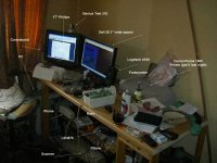
can u help me fix this problem Sir Carlos? I attached some pictures of my project. Thank you in advance.
Regards,
Marjohn


Sir Carlos,
Good Day to you Sir,
I have build a prototype of your dx precision 1 and on my initial testing i had this values:
2sa1943:B=.312V, C=64.1V, E=.841V
2sc5200:B=.223V, C=63.3V, E=.225V
BD139:B=.810V, C=.829V, E=1.448V
2sa1837:B=1.439V,C=63.9V E=.842V,
2sc4793:B=.822V, C63.4V, E=.225V
voltage reading across 100 ohms in series with +/- rails
+6.02V
-5.29V
positive rail +69.3V
negative rail - 69.4V
offset = .311V.
I know that there is a problem with my circuit but i dont know exactly where?
can u help me fix this problem Sir Carlos? I attached some pictures of my project. Thank you in advance.
Regards,
Marjohn
thanks AndrewT but those heatsinks are not touching any other components and also are insulated from the transistors.are the To220 heatsinks isolated from all other components?
Base emitter voltage into the 2SC5200 seems wrong
looks you have a short in between base and emitter....this may disturb the bias control as you are slightly underbiased.
Off set should be reduced adjusting the long tail resistances.....or...the current sink emitter resistances.... i do not remember the value but seems it is 68 to 82 ohms resistances... these two transistors below the circuit, down left, connected to the differential pair emitter.
I am sorry, new computer and i have no files nor schematic to give you part numbers.
You should check transistors removing them from the circuit and testing them...TILL you find an error...if off set remains, then proceed the bias adjustment and tweak the long tail resistances if needed till you have less than 25 milivolts...usually it is lower than 10 milivolts (of set)
There's no big magic.... now it is time to work hard, removing transistors and testing them outside the board...to check if values are correct, if NPN transistor are installed in the correct place..also the PNP ones.... to observe diodes polarity (if you have them)... to search for errors.
regards,
Carlos
- Status
- Not open for further replies.
- Home
- Amplifiers
- Solid State
- Dx Precision, finally released... now debugged and better than HRII