Movin' right along....
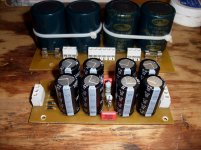
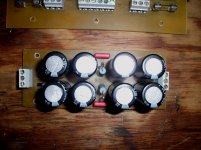
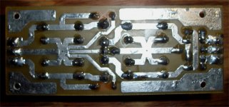
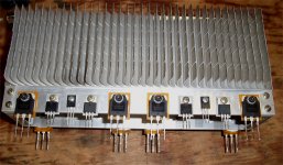
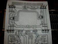
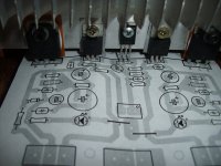
The HVPS is done( photo 1). It took a pinch of table salt 😀😀 Really!! , to speed up the etch to burn away the double sided board (I really wanted single sided material 🙁 ). The CL in the salt combines with CU++ that the acid liberates to form CUCL2. Speeds the etch up X- 2 to 3 or more. Pittless perfection in 3 minutes.. (photo 2) is the C-C-R-C-C ,the Nikko will be happy. (Photo 3) is the "starring" on this one.. which will go to the main star.
Now for the amps ... all I have to do is build those OPS boards. Since they are the "burning" part of the amp , this teflon FR-4 will allow for some good bonfires 😀. I took a blowtorch to this stuff and it took over 20 seconds to delaminate..whoa !! Perfect DIY material. I might etch these ones with Vinegar/peroxide and salt (this also works VERY well - and is safer).
The C-R-C HVPS will be something that can be used with the "kit". For safety, both of this nikko's driver/voltage stages will have fusible links or very low value resistors to blow (photo 4 - arrows) ... just in case. Whatever goodness becomes of the Nikko/AX.... will become the "kit" (after I listen and approve) , I am trying to get the size down to 150 X 75mm as well ... bracket and direct mount.
OS
Attachments
Tapping sucks...
John was right , but I HAVE the taps ... so I could not resist. Sort of like a 12 pack of beer in the fridge 😀 . Got away with just 8 holes re-tapped for 6-32's , reused the original holes for the to-220's and had to make 2 new holes for the 4-40 threaded Vbe devices. Below is the outcome , it will be nice (if my PCB's fit perfect).
OS
Attachments
Just being careful...
I DON'T like to DIY twice. Stare at your board layout for a while , errors will become apparent. Not all are electrical , physical considerations are just as bad.
This amp is harder than the typical DIYA build , with compact OEM layout and airflow factors ... good practice for an ampman. 😀 The exact PCB print fit right on the OPS assembly perfectly (below) ... Now , I am really "good to go". 😎
edit: Vbe trimmer clearance (below 2) .. another factor... Real good practice to get the "kit" right. This will not be your normal "retrofit" ... it will be better than original and actually look OEM.
OS
Attachments
Last edited:
April kit OPS
I have the output stage done for the AXKIT. Vbe ,drivers, 4/ to-3P or to-264 devices can be mounted either with bracket or flat direct. This was goal 1 , to satisfy the beginners (bracket) and the more advanced. At 100mm , a 125mm flat heatsink or one of the fancy aussie conrad's will do nicely. (below 1)
In a way , Carlo's is right ... this does take some time. But , this IS NOT a prototype ... I'm way past that point..
To dispel a common myth about rail currents "cancelling" with tight parallel routing (or twisting the rail wires together) , this layout will not have this fallacy incorporated. In fact ,I recommend just having rails separate from small signal zones and any sensitive ground returns. The amps native PSRR and the cap multipliers are much bigger factors in the PS's contribution to THD. Noise and hum is best dealt with by using the split ground method (G1 /G2- like the present mongrels). I've seen these methods for both the rails and grounds used in many mid/high quality OEM's , as well.
Not everyone will have a dual center-tapped secondary or 2 independent supplies , so this setup will have a handy jumper to run the whole "deal" off
one unregulated power supply. Simplicity is paramount , so I will drop the cascode and just run a straight input pair with typical 2Q current mirror. I tried the wilson mirror , and the audio benefits were not there.
What we will have is a 120 watt blameless with TMC and cap multipliers that is cheap ($35-40 a pair), can use whatever parts you have around and is made with "bulletproof" FR-4. 🙂
OS
Attachments
Member
Joined 2009
Paid Member
My gosh, the Elves have been busy whilst I was away, looking very professional.
forgive me if I've missed the relevant post - but how do you find the impact of cap mux on the sound ? I know Hugh doesn't like them on ClassAB, Nelson uses them on ClassA,. I assume it's important to have a good quality cap after the cap mux, i.e. between the cap mux and the OS ?
forgive me if I've missed the relevant post - but how do you find the impact of cap mux on the sound ? I know Hugh doesn't like them on ClassAB, Nelson uses them on ClassA,. I assume it's important to have a good quality cap after the cap mux, i.e. between the cap mux and the OS ?
cap mux ??
cap mux ?? Explain that and I will try to give a concise response. "mux" is multiplexer ??
OS
cap mux ?? Explain that and I will try to give a concise response. "mux" is multiplexer ??
OS
Banned!
You are banned from this server with the reason of:
??http://files.diyaudio.com/forums/images/smilies/confused.gif
You are banned from this server with the reason of:
??http://files.diyaudio.com/forums/images/smilies/confused.gif
I have the output stage done for the AXKIT. Vbe ,drivers, 4/ to-3P or to-264 devices can be mounted either with bracket or flat direct. This was goal 1 , to satisfy the beginners (bracket) and the more advanced. At 100mm , a 125mm flat heatsink or one of the fancy aussie conrad's will do nicely. (below 1)
OS
HI OS,
Thanks for doing the work to allow the greater flexibility in choosing heatsinks.
Mark 🙂
If you meant "multiplier"
1 . general PSRR of the whole amp is increased by at least 6db. You can hear this as a "dual mono" effect. Source with a lot of separate L/R material is better on this. I was skeptical of the benefits until I built the PB250 (integrated multipliers) ... I never heard the band "YES" until I heard it with the 250. I jumpered the multipliers to A/B and "YES" lost some definition. Electrically , it is also nice to see mV ripple at your sensitive voltage stage while you do "blasphemy" to your output stage.
This time around I will have a separate supply as a option. Layout is the same as the Nikko Alpha with the added multipliers as opposed to Nikko's simple R/C decoupling. Multiplier decoupling will be separate as well.
OS
Banned!
You are banned from this server with the reason of:
??http://files.diyaudio.com/forums/images/smilies/confused.gif
Sorry , I had the university of red commie land port scanning and downloading everything , so I banned 116.xxx.xxx.xxx and 117.xxx ... the whole IP range , Google's range is also banned... 66.xxx all of it, for disobeying robots.txt. 🙁
All other ranges are now open. (except those above) 😀
OS
Member
Joined 2009
Paid Member
Hi - yes I mean multiplier, I was lazy typing, feel like shyte today, sore throat etc.
So you are talking about a cap mult. for the front end only, or also including the power stage ? - sorry for being a bit slow
So you are talking about a cap mult. for the front end only, or also including the power stage ? - sorry for being a bit slow
or also including the power stage ?
Nope , that would entail a darlington/njw0281/0302 monster multiplier 😱 Not diy friendly. The way it is (below 1) is "dang" good enough for any hobbyist.
1 and 5 ppm @ 1 and 20khz / 100w/8r. (final schema - most likely the exact as the final documentation).
OS
Attachments
Member
Joined 2009
Paid Member
ah, now that makes more sense since it's feeding a Class A stage rather than the ClassAB output.
Just class A up to the MJE drivers. 4 outputs are class AB, biased to 70ma each.
TMC feeds the Xover "glitch" back to Cdom (local FB) lowering THD to PPM.
Circuit has no turn-on "thump" , ran it 24/7 for 4 months ... confident the resulting project will be 110%. Also , Thermally stable from a cold winter day ( 0c) to summer (35c) w/ 10ma - 2-3mv OPS Re ( a safe amp) I went up about 10pF (total Cdom) above the first signs of capacitive ringing to compensate this amp. (Very stable - slightly overcompensated). 🙂
OS
Hi OS
I'm playing with your mongrel sims as a learning exercise, and I was wondering how you are simulating/plotting loop gain?
I'm playing with your mongrel sims as a learning exercise, and I was wondering how you are simulating/plotting loop gain?
loop gain and PSRR
1. Comment out " ( ; ) tran 0 {simtime} {dlytime} {numsampl} ... add the semicolon. (disabling it)
2. Change V4's (or the input source) expression to SINE(0 {sqrt(0)} {freq}) , essentially.. turning it off. Change feedback source to "AC1"
3. Create or uncomment " .ac dec 100 1 10e7" ( will sweep "ac1" from 1hz-100mhz)
4. Simulate... with the "add trace" below plot , add " -V(vout)/V(a) "
Closed loop gain + unity gain freq. will be known from the resulting bode plot. (below 1)
PSRR - make feedback source "AC 0 " again , add "AC1" to both rail sources (+/- 58 or whatever they are) Keep the " .ac dec 100 1 10e7" , probe the rails and the amp output for precise PSRR. (below 2) REAL GOOD... -100db+ (red/blue = rails / green=output)
OS
Hi OS
I'm playing with your mongrel sims as a learning exercise, and I was wondering how you are simulating/plotting loop gain?
1. Comment out " ( ; ) tran 0 {simtime} {dlytime} {numsampl} ... add the semicolon. (disabling it)
2. Change V4's (or the input source) expression to SINE(0 {sqrt(0)} {freq}) , essentially.. turning it off. Change feedback source to "AC1"
3. Create or uncomment " .ac dec 100 1 10e7" ( will sweep "ac1" from 1hz-100mhz)
4. Simulate... with the "add trace" below plot , add " -V(vout)/V(a) "
Closed loop gain + unity gain freq. will be known from the resulting bode plot. (below 1)
PSRR - make feedback source "AC 0 " again , add "AC1" to both rail sources (+/- 58 or whatever they are) Keep the " .ac dec 100 1 10e7" , probe the rails and the amp output for precise PSRR. (below 2) REAL GOOD... -100db+ (red/blue = rails / green=output)
OS
Attachments
Last edited:
Thanks, much appreciated!
(l've been really struggling with how to evaluate loop gain, and also appreciate how to evaluate PSRR)
(l've been really struggling with how to evaluate loop gain, and also appreciate how to evaluate PSRR)
Last edited:
Ost,
I am trying to read your sim plots.
I'm struggling.
Could you talk me through them?
A bigger pic with a bit more resolution would help with "reading" those colours.
I am trying to read your sim plots.
I'm struggling.
Could you talk me through them?
A bigger pic with a bit more resolution would help with "reading" those colours.
- Home
- Amplifiers
- Solid State
- The MONGREL (supersym II)