I'm going to try an build an output stage in a pre with a ccs load. What was wondering is would I still need to apply grid bias to it?
Thanks
Nick
Sent from my Garminfone using Tapatalk
Thanks
Nick
Sent from my Garminfone using Tapatalk
The CCS will be on the anode, right? What are you going to do with the cathode? That's what's going to determine what the grid will need.
Well I was assuming the dcs would take the place of the grid bias.
I was just going to have the cathode tied to ground.
I have never used any ccs so I'm a newbie here.
Sent from my Garminfone using Tapatalk
I was just going to have the cathode tied to ground.
I have never used any ccs so I'm a newbie here.
Sent from my Garminfone using Tapatalk
No, the ccs goes either in the anode or in the cathode lead. Depending on the implementation, you'll need to set the grid bias.Well I was assuming the dcs would take the place of the grid bias.
If you build a triode amplifier with a CCS instead of a plate load the current through the tube will be fixed at the CCS current. The bias applied to the tube will then set the idle plate voltage. With no bias, the tube attempts to conduct fully. It is limited to the CCS current so the plate voltage goes to a low value (saturation). Too much negative bias results in cutoff and the plate voltage goes to the B+ voltage. The bias can be the usual cathode resistor or LED, or it can be a negative voltage applied to the grid, but it still needs to be there.
CCS loading a pentode generally leads to unstable operation. Ideally both are CCS's and the highest (even by a microamp) valeued CCS will win. In reality neither are perfect CCS's but the tube is generally less perfect and will drift. This makes a temperature dependent flip flop. There are ways to cheat though.
CCS loading a pentode generally leads to unstable operation. Ideally both are CCS's and the highest (even by a microamp) valeued CCS will win. In reality neither are perfect CCS's but the tube is generally less perfect and will drift. This makes a temperature dependent flip flop. There are ways to cheat though.
Oh man, I feel stupid.
I see the error of my ways.
Sorry for the stupidity guys and thanks for helping me see the light, LOL.
Nick
I see the error of my ways.
Sorry for the stupidity guys and thanks for helping me see the light, LOL.
Nick
If you build a triode amplifier with a CCS instead of a plate load the current through the tube will be fixed at the CCS current. The bias applied to the tube will then set the idle plate voltage. With no bias, the tube attempts to conduct fully. It is limited to the CCS current so the plate voltage goes to a low value (saturation). Too much negative bias results in cutoff and the plate voltage goes to the B+ voltage.
Thanks George for a crystal clear explanation! Makes perfect sense now that I think about it.......I suppose this is another way of stating Eli's usual explanation: take plate voltage, plate current and grid voltage, fixing any two will determine the remaining variable.
hey-Hey!!!,
Let's look at it graphically along the lines of Tubelab's explanation. take your triode plate curves and draw a horizontal line at the CCS's current. Now where along that line do you want the plate voltage? With a grounded grid and cathode the plate voltage will be where the grid=0V crosses your horizontal current line. Make the grid VERY negative and plate voltage will sit at B+( B+ not being infinite, and assuming the tube will stand the dissipation ). You'll need to apply grid bias to deliver plate voltage somewhere between B+ and saturation at grid=0V.
cheers,
Douglas
Sorry for the stupidity guys and thanks for helping me see the light,
There are no stupid questions....... Only someone else who had the same question in his mind that took the time to hook it up and play. Looking at it from a load line perspective makes perfect sense now, but I didn't quite get the concept 10 years ago when the 10M45 first came out. I had to play with them for a while. The gate stopper was not (and still isn't) specified on the IXYS data sheet, so my first experiments were great TV jammers!
Note the schematic of the input stage of the Tubelab SE. The pot (or some means of adjusting the bias) is required on high Gm tubes like the 5842 where none of them actually match the published curves. The SSE used a fixed resistor since the 12AT7 is much more consistent.
TubelabSE
Another stupid question:
Does it make sense to use a CCS in the cathode of a PP amplifier's output tubes? I mean the cathodes tied together and a CCS is connected between this point and the ground. This could be a kind of cathode bias.
Does it make sense to use a CCS in the cathode of a PP amplifier's output tubes? I mean the cathodes tied together and a CCS is connected between this point and the ground. This could be a kind of cathode bias.
Another stupid question:
Does it make sense to use a CCS in the cathode of a PP amplifier's output tubes? I mean the cathodes tied together and a CCS is connected between this point and the ground. This could be a kind of cathode bias.
hey-Hey!!!,
It has been done. It will only allow Class A operation( so if you've got an AB operating point, it isn't optimal ). If you run pentode finals, the screen current component will need to be accounted for.
cheers,
Douglas
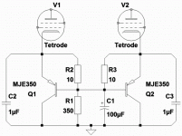
Would this work? 1st 65mA goes into the bias circuit, anything over 65mA bypasses...
Assuming like a 50mA+50mA quiescent situation???
I prollyshoulda thrown 150R in series with each collector, stop a runaway at 345mA.
Maybe this is no better or different than Zenier bypass...
Assuming like a 50mA+50mA quiescent situation???
I prollyshoulda thrown 150R in series with each collector, stop a runaway at 345mA.
Maybe this is no better or different than Zenier bypass...
Attachments
Last edited:
Does it make sense to use a CCS in the cathode of a PP amplifier's output tubes?
As stated before this forces class A operation and works best with triodes. Attempting to drive the triodes into A2 causes distortion. Within those constraints the output tubes function as an LTP. This affords the advantages of LTP operation the best of which is immunity from common mode noise.
I have built an amp that runs a 6SN7 LTP driving another 6SN7 LTP driving a pair of KT88's in triode LTP. It produces a very clean 12 watts per channel
I don't understand why are LTP with CCS and Class A related. One side of the LTP can be driven into cutover, then the other side will carry double current, i.e. the full CCS current. I can imagine even an AB1 operation.
I don't understand why are LTP with CCS and Class A related. One side of the LTP can be driven into cutover, then the other side will carry double current, i.e. the full CCS current. I can imagine even an AB1 operation.
AB1 full power has one tube conducting more than the sum at idle. With CCS setting this sum of idle currents there is no way to drive into AB territory...it just can't happen.
cheers,
Douglas
Another stupid question:
Does it make sense to use a CCS in the cathode of a PP amplifier's output tubes? I mean the cathodes tied together and a CCS is connected between this point and the ground. This could be a kind of cathode bias.
LTP for class A output?
I did that for a guitar amp. Light bulb in cathode, one grid grounded, another -- signal input. Nice sound.
- Status
- Not open for further replies.
- Home
- Amplifiers
- Tubes / Valves
- Bias using a ccs as an anode load