What is also interesting is that the audio range effects of signal cables neve seemed to have taken much interest. Most of the research are in the higher frequency ranges geared for long distance transmission which were communication orientated. Purely by perceived market demand. For people working in the audio range, it's like scrapping around for information pieces and trying to make some sense out of them. Hard work and little return.Interesting read. Thanks for the link.
I was particularly interested in several items.
1. The analysis showing how the actual load impedance affects the signal transmission to the load. (perhaps that was forgotten)
2. His explanation that even though the line starts to approach the 50 or 75 ohm impedance within the audio band, that can be ignored for audio up to 2 thousand feet long. Doesn't seem to be internally consistent.
I always have concerns whenever an article is written to attempt to debunk something..they never work out right..
Cheers, John
What is interesting is that interconnects having the same impedance measurements still sound different if the structure is different. Trying to piece things together is like looking for a needle in a hay sack. Up to now, the trend seems like using hot side conductor size of #24~#28 provides optimum results. More current capability just requires using multiples of them. The sound gets a bit fuzzy if the conductor size goes larger or smaller with the same total conductive cross section.
Last edited:
Hmm, in the OCOS report, they talked about the possibility of L/R=C/G.From figure 2 the velocity of propagation of DC is 1% of the speed of light?
Is there really a .5us delay between the high and low audio frequencies in a 1m cable?
The Telegrapher's Equation is bit more complete.
So what I was trying to mention on the Blowtorch thread is going on here.
However it does explain G and how the mu metal was used!
The idea of skin depth certainly explains somethings. Also non insulated strands do cause certain audible effects where are generally associated with a slightly rough but somewhat warm sound. Similarly, if the conductor is too large, it will also produce a slightly rough sound. However these are much less of concern if the overall sound image is well defined and focused.
You also might find this paper interesting:
"Cables, Transmission Lines, and Shielding for Audio and Video Systems"
http://audiosystemsgroup.com/TransLines.pdf
More (about 60) of Mr. Brown's papers at Audio System Group.
Audio Systems Group, Inc. Publications
Jim Brown is the AES committee chair on EMI/RFI (EMC).
Thank you. Very nice indeed. For some reason, he tends to stress "loop area"....hmmm, I've heard that somewhere....😛 and, I like it..
A few interesting points..
Quote:
""When transmission line effects are minutely small, as they are in the vast majority of cables carrying audio signals, the pulses travel at the speed of light.""
Hmm..I don't think so. But remember, how would one test this?
Quote:
"" A relatively short length of cable shows no measurable transmission line effects for low frequency signals.""
Two things..first,how does one measure it? , and second, for audio low microsecond delays are generally considered of no interest..so in general, why worry about something that has been assumed makes no difference.
Quote""VF = 1/sqr(ε) where ε is the dielectric constant relative to free space.""
More rigorously, it is 1/sqr(epsilon mu), adding permeability into the fray..
Here is where everybody is getting it mixed up, including Jim Brown...
Quote:
""The ratio between these basic parameters,
established by the cable’s physical construction, establish its characteristic impedance, (ZO)
and in combination with the loss parameters, the velocity at which the signal will move along
the line (called its velocity of propagation) (VP). Mathematically,
note: the equation fell apart here when I pasted it...it is the Zo =sqr(r +jwL/g + jwC)
At high frequencies, the equation simplifies to ZO =sqr(L/C)
For any given cable type, ZO and VP are essentially constant above about 50 kHz, but at low frequencies, vary considerably with frequency before settling to their high frequency values!
Everybody is confusing this equation as meaning the characteristic impedance of the cable...IT IS NOT.
Here is a correct definition:
""Zo has ohms as its unit, and it is NOT on a per-unit-length basis. It represents the input impedance of the entire line of infinite length as seen by the generator terminals..." (italics, bold, underline mine)
Albert Shadowitz, "The Electromagnetic Field", 1976, pages 564-565..Dover Publications, New York.
For non infinite lengths of cable, the equation being used by Jones is not a correct expression.. Using it as an expression for the characteristic impedance of a cable can result in some rather interesting conclusions, such as the wildly varying characteristic impedance and propagation velocity graphs presented in another paper.
Quote:
""In other words, the effect of the line is to simply attenuate the signal. Another way of looking at it is to say that a proper termination makes
the line act as if it were infinitely long""
That was my example of the 8 ohm z cable with an 8 ohm resistive load..the amp sees the pure 8 ohm as a load.
Quote:
""In any electromagnetic field, the energy is continuously being traded (on each quarter cycle of the waveform) between the electric field (that is, charging the capacitance) and the magnetic field (established by the inductance).""
That is not the case for propagating waves. What has just been described is the e-field and M field as 90 degrees out of phase which is consistent with standing waves created by a reflection.. There is no net power flow when they are 90 degrees out.
In a travelling wave, the e amd M field are not trading energy, they peak at the same time, are zero at the same time. Curiously, this is what Hawksford stated incorrectly as well..hmmm.
Other than the few (to me, minor) gaffs, he is an excellent source. His discussions on shielding and EMC considerations should be required reading..
He would be a great read if he considered the mispmatched impedance model (normally used in audio) and wrote about it..
Cheers, John
Last edited:
The last time I looked, one valid definition of characteristic impedance is that it is the input impedance of a line of infinite length. It is also the impedance which correctly terminates a line of finite length i.e. replaces the rest of the infinity. Do you have some other, non-equivalent, definition? In what sense is Z0, as given by the full formula, not the characteristic impedance of the cable? You keep saying that everybody else is wrong, but you have not presented your claimed alternative. Are you being profound, picky, or just wrong?
If you put an 8R load on an 8R cable, you will see 8R. Is anyone disputing that? You keep stating it as though someone disagrees. What you may be forgetting, however, is that very few people have access to an 8R cable across the whole audio range. What people may call an 8R cable is only that towards the top end of the audio range and above.
If you put an 8R load on an 8R cable, you will see 8R. Is anyone disputing that? You keep stating it as though someone disagrees. What you may be forgetting, however, is that very few people have access to an 8R cable across the whole audio range. What people may call an 8R cable is only that towards the top end of the audio range and above.
The last time I looked, one valid definition of characteristic impedance is that it is the input impedance of a line of infinite length.
I quoted directly from Shadowitz. As quoted, it only the terminal impedance, and as quoted it is NOT the characteristic impedance. Perhaps it is time to take another look, as the distinction can certainly be missed.
It is also the impedance which correctly terminates a line of finite length i.e. replaces the rest of the infinity.
For that, I agree.
However, my analysis does not consider a correctly terminated line. In fact, I've stressed continually that it is indeed the mis-termination that is the issue, and that the effects of that mismatch is not being considered.
Perhaps you'd be happier asking that question of Shadowitz.Do you have some other, non-equivalent, definition? In what sense is Z0, as given by the full formula, not the characteristic impedance of the cable?
Using the two terminal model of an infinite transmissiion line as the definition of characteristic impedance of a finite one is incorrect. Verbatim quotes are now insufficient?You keep saying that everybody else is wrong, but you have not presented your claimed alternative.
And I have presented my model and why it is necessary.
Profound? maybe... the jury is still out.Are you being profound, picky, or just wrong?
Picky? Many times, yes.
Wrong? Well, that's always a possibility. However, being proven "wrong" by using an incorrect equation to prove me incorrect just doesn't cut it.
Keep stating it? Where? I pointed out once that using the proper termination removed the line capacitance from the amplifier output terminals. The presented alternative, that of modelling the line via r/jwc, does not do that.If you put an 8R load on an 8R cable, you will see 8R. Is anyone disputing that? You keep stating it as though someone disagrees.
Actually, that is incorrect. do a search on cat5e. Quite a few people will parallel multiple runs of it in some hilarious braiding configurations they swear by. When in fact, they're just paralleling lots of 100 ohm orthogonally twisted wire pairs to get down to 8 ohms.What you may be forgetting, however, is that very few people have access to an 8R cable across the whole audio range. What people may call an 8R cable is only that towards the top end of the audio range and above.
I did the same when I had to push a 40 volt quench heater current into a cryostat to drive a zero inductance stainless heater. I paralleled 6 full cat5e cables up to the warm to cold transition, switched to a half inch wide stripline to get to the supercon mag. I needed to drive 10 uSec risetime with varying pulse width. I can state categorically, that paralleling cat5e in this fashion does indeed present the expected characteristic impedance. It worked perfectly.
It is somewhat disingenous to attack the messenger with "profound, picky, or wrong" as you did. Up till then, you've been rather nice.
So, have you evidence that Shadowitz is incorrect?
Why are you not discussing the ramifications of the load mismatches typical of audio, the entity I have based the entire derivation around?
Cheers, John
Last edited:
If one connects two 100ohm cable pairs in parallel, the net impedance is 50ohms. Is that correct?
Connect 25pairs of cat5 in parallel and you end up with 4ohm. Terminate with a 4r0 resistor and the line behaves as if it were infinitely long. Is that correct?
Does the bulk of 25pairs require a modification factor that will result in something other than 4ohm?
Connect 25pairs of cat5 in parallel and you end up with 4ohm. Terminate with a 4r0 resistor and the line behaves as if it were infinitely long. Is that correct?
Does the bulk of 25pairs require a modification factor that will result in something other than 4ohm?
If one connects two 100ohm cable pairs in parallel, the net impedance is 50ohms. Is that correct?
In theory, yes. In practice, it worked extremely well for me.
Yes. I actually used 24 pair, 6 cables total...but the waveform was extremely well behaved, had a 10 uSec rise with a flat top extending hundreds of microsecond out. It duplicated well for my zero inductance 4 ohm room temp load as well as the cold load.Connect 25pairs of cat5 in parallel and you end up with 4ohm. Terminate with a 4r0 resistor and the line behaves as if it were infinitely long. Is that correct?
Does the bulk of 25pairs require a modification factor that will result in something other than 4ohm?
I'm not sure what the question is...I had the tech tie wrap the bundle every 3 or 4 feet, no problemo.
If you need a different Z, I don't see an easy way of modifying the 25 pair to get a different value..just use a different number of cables.
As a heavier guage alternative, you could use lots of 22 guage zip, each with a different twist pitch...be kinda ugly though..
Cheers, John
Is everyone still talking about characteristic impedance in the audio range?
I am.
As I pointed out, the equation that is being used is not the equation for characteristic impedance, it is the equation for an infinitly long line as seen by the two terminals..Using it out of context makes for some interesting graphs as well as interesting conclusions.
Once a t-line has been terminated by a mismatched load, the analysis becomes "different". This is what I am stressing.
When the load impedance matches the line, the inductive storage in the line is exactly equal to the capacitive storage.
When the load impedance is below the line, the inductive storage swamps the capacitive storage. (speaker runs typically)
When the load impedance is above the line Z, the capacitive storage swamps the inductive. (IC's typically, and speakers when the drivers unload and go high impedance..)
Cheers, John
It seems the difficulty is in finite length and still trying to make things as ideal as possible.
It seems the difficulty is in finite length and still trying to make things as ideal as possible.
I believe it to be just a case of figuring out what is relevant to audibility, then working out how to control it.
Seems simple enough, no?? 😉
Cheers, John
Sorry, I didn't mean to be rude. I genuinely don't know whether you have identified a weakness in the standard picture, or whether you are misunderstanding the standard picture.jneutron said:It is somewhat disingenous to attack the messenger with "profound, picky, or wrong" as you did. Up till then, you've been rather nice.
I have just referred to my copy of Shadowitz, and as far as I can see he is saying the same thing as me. Z0, given by the formula, is the characteristic impedance of the line. He says this at the bottom of page 563, and gives the normal expression on page 564. As far as I can see it is you that is differing from Shadowitz. I have looked at "Fields and Waves in Communications Electronics" by Ramo, Whinnery and van Duzer and they seem to say the same.
If I understand you correctly, you are saying that Z0 is not characteristic impedance but something else? If so, what should we call Z0? How do we calculate characteristic impedance, if the normal formula does not give this?
Sorry, I didn't mean to be rude. I genuinely don't know whether you have identified a weakness in the standard picture, or whether you are misunderstanding the standard picture.
For audio, the weakness is not considering the gross impedance mismatch that occurs at the end of IC's and speaker runs.
When LF audio is pushing through a 100 ohm cable to a load that is 2 to 8 ohms, the current/voltage relationship within the wire is NOT a result of the wires characteristic impedance relation, but forced upon it by the load. A consequence of that, is that the inductive storage within the line is much different than the natural one the line would have if it were terminated matched.
The use of the terminal impedance equation as a substitute for the actual characteristic impedance provides incorrect results, like the prop velocity or characteristic impedance graph Jones provided.
I have just referred to my copy of Shadowitz, and as far as I can see he is saying the same thing as me. Z0, given by the formula, is the characteristic impedance of the line.
Truly a puzzle.
I copied verbatim his statement on the bottom of page 564. I have the paperback Dover published in 1988, they say and I quote: ""This dover edition first published in 1988, is an unabridged, corrected republication of the work origionally published in 1975 by the mcgraw hill book co..""
So very clearly, he has identified that equation as NOT the equation for the transmission line characteristic impedance. Is yours a later or earlier edition. If mine is later, I really wish they had greyed in the changes like the NEC does, it makes it easy to track corrections and changes..sigh.
AHA..My book says, on page 563 at the bottom.., ""Zo is called the characteristic impedance of the line..""
So here he calls it the characteristic impedance of the line, but then he states it's not on a per unit length basis but instead the input impedance of the entire line.
He says this at the bottom of page 563, and gives the normal expression on page 564. As far as I can see it is you that is differing from Shadowitz.
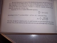
I took a pic of the page... Is this the same as yours?edit: I believe it is..., comments added..
If I understand you correctly, you are saying that Z0 is not characteristic impedance but something else? If so, what should we call Z0? How do we calculate characteristic impedance, if the normal formula does not give this?
I'm saying that the calculation which includes the R and G term is exactly what Shadowitz says it is, and I agree that what he says it isn't, isn't.
I've used sqr(L/C) in my calculations of settling times, as the primary interest is in how the termination mismatch builds up either inductive or capacitive energy storage that is not consistent with matched loads.
The characteristic impedance of a transmission line is the relationship between the current propagating in the line and the voltage propagating.
It is defined as the equivalancy between the energy stored in the inductance of the cable and the capacitance of the cable.
1/2 C(V squared) = 1/2 L(I squared)
CVV = LII
VV/II =L/C
(V/I)(V/I)=L/C
ZZ = L/C
Z = sqr(L/C)
edit: the sentence which I copied verbatum earlier is on the top of page 565, I didn't think that I'd have to take that picture as well..
Cheers, John
Attachments
Last edited:
I have the same edition of Shadowitz as you have. On p563 he defines what he means by Z0, the characteristic impedance. On p564 he gives a formula for it.
When a line is mismatched the analysis does not change, although the algebra may get harder. You just have to use the formula for input impedance, given characteristic impedance and load impedance. Shadowitz gives the 'no attenuation' approximation for this at the top of p571 (and the bottom of p573). The full formula, valid for all lines, is given by R, W and D on page 247 - it includes the attenuation and has hyperbolic trig functions instead of normal trig. However, for most normal audio purposes the simpler formula is fine as lines are short. If you are calculating a transient bouncing back and forth along a short line (which I believe may be your approach) then you have to use the full formula, which Shadowitz does not give.
I believe you have misunderstood Shadowitz. The sentence at the bottom of p564 about Z0 not being on a per unit-length basis makes perfect sense. Z0, as defined, applies to the transmission line - the whole of it, and every part of it - it is a property of the line, just as 377R is a property of free space.
If you correctly use the standard theory you will get the correct answer. Part of the problem may be that engineers often quote approximations without saying that they are approximations.
I have the same edition of Shadowitz as you have. On p563 he defines what he means by Z0, the characteristic impedance. On p564 he gives a formula for it.
The actual characteristic impedance of a cable is not length dependent. That is why he stated his Zo was for the entire line of infinite length.
When a line is mismatched the analysis does not change, although the algebra may get harder. You just have to use the formula for input impedance, given characteristic impedance and load impedance. Shadowitz gives the 'no attenuation' approximation for this at the top of p571 (and the bottom of p573).
You just drifted into the "throughout this chapter we will restrict ourselves to the usual high frequency case where Zo is a real quantity.."
I'm speaking of LF in the audio domain..
The full formula, valid for all lines, is given by R, W and D on page 247 - it includes the attenuation and has hyperbolic trig functions instead of normal trig.
page 247 is statics in my book. Was that a typo?
However, for most normal audio purposes the simpler formula is fine as lines are short. If you are calculating a transient bouncing back and forth along a short line (which I believe may be your approach) then you have to use the full formula, which Shadowitz does not give.
Shame on him..
My approach considers the line reaching the load based current/voltage relationship. It requires multiple transits for the line to establish those values.
I believe you have misunderstood Shadowitz. The sentence at the bottom of p564 about Z0 not being on a per unit-length basis makes perfect sense. Z0, as defined, applies to the transmission line - the whole of it, and every part of it - it is a property of the line, just as 377R is a property of free space.
He stated that Zo is not a short length value, but one of an infinite line.
Anybody know if he's still alive?
Part of the problem may be that engineers often quote approximations without saying that they are approximations.
I certainly take exception when somebody uses the infinite length equation when referring to characteristic impedance of a section of cable. Getting wacky prop velocities and impedances is an interesting result of such a mess..
Cheers, John
The actual characteristic impedance of a cable is not length dependent.
He stated that Zo is not a short length value, but one of an infinite line.
I'm sorry, I don't understand how you reconcile these 2 statements. If it's not length-dependent, then it doesn't need to be infinite.
w
Z0 applies not only to the infinite length line, but any finite portion of it too. It is a property of the line. Maybe this is your point of confusion?jneutron said:The actual characteristic impedance of a cable is not length dependent. That is why he stated his Zo was for the entire line of infinite length.
No, I never said Z0 is real.You just drifted into the "throughout this chapter we will restrict ourselves to the usual high frequency case where Zo is a real quantity.."
p247 is in the other book I mentioned. Sorry, I should have made that clearer. I could not refer to Shadowitz for that formula as he doesn't give it.
No he did not. You are misunderstanding him. Z0 applies to any length line. It is the input impedance of an infinite length (as he says). It is the input impedance of any finite length terminated in Z0 (as he says). It is the characteristic impedance of the line - not that specific line of that specific length, but any line of that specific type at that specific frequency. If I chop a line in half, each half has exactly the same characteristic impedance as the line I started with. If I match a line, or mismatch it, the line still has the same characteristic impedance (although the input impedance may change).He stated that Zo is not a short length value, but one of an infinite line.
For a while I suspected you misunderstand the theory. Now I am sure you misunderstand. Please review your understanding of transmission lines; perhaps try a different book? Shadowitz is a good book, but there are others so maybe you will find one which explains things better for you.I certainly take exception when somebody uses the infinite length equation when referring to characteristic impedance of a section of cable.
If I chop a line in half, each half has exactly the same characteristic impedance as the line I started with.
Like a hologram!
- Status
- Not open for further replies.
- Home
- Design & Build
- Parts
- Interconnect cables! Lies and myths!