I take the time to read a post.LOL...AndrewT likes stirring the sh$T pot.
It has my attention.
I expect it to be relevant !!!!!!
If the poster has no intention of giving information then what is the point in any of us reading his uninformative post?
What is the purpose in posting non information?
Hi,
another day has passed and still no explanation of what was measured, nothing on how the measurements were done, nor how to put values on the wavy lines.
You didn't really expect anything coming out of that, did you? 😉
jan didden
No. Reread my post #763. Sqrt(L/C) is not true for low frequencies, not misapplied as you imply, but not true. Circuit theory shows that the full correct expression involves R and G, as well as L and C. See any decent graduate textbook on transmission lines.
I am well aware of the full correct expression. As well as the textbooks.
The textbooks actually need updating. edit: especially skin theory..quite a few of the beam/magnet physicists here have gotten into trouble using what is in the textbooks. The best one I know has NO textbooks. The reason: he derives all he needs from Maxwell's equations, that way he knows it's correct. (and sonufagun...he's always right..)
The current website, characteristic impedance and .00001 wavelength line lengths really are silly put together. Move on, I won't bother you anymore.
Hmm..
take a hot amplifier, a single driver 8 ohms, and let's build a constrained cable 10 meters long with a characteristic impedance of 8 ohms using a dielectric with a relative permittivity of 3. (edit:almost forgot, make the inner core a braid as well, to remove the 15 nH per foot from the fray) (note that my avatar is the magnetic field intensity of that double braid coax)
The cable will have a capacitance of 220 pf/ft, and an inductance of 14.1 nH per foot.
The total cable capacitance will be 32.8 feet times 220, or 7223 pf, total inductance of 462 nH.
Some amplifiers will have trouble driving this load, we all "know" why. The capacitance loading at the output.
However, if I replace the driver with a pure 8 ohm load, what happens? The amp sees a pure resistance and does not oscillate.
A rudimentary cable model does not predict this.
The reason? The speaker unloads where the amp needs the load the most. edit: and when the load impedance is larger than the cable characteristic impedance the cable takes on a capacitive nature. When the load goes below cable z, the cable takes on an inductive nature..
It is very important to use a model which is as complex as it needs to be, as well as as simple as it needs to be.
Cheers, John
Last edited:
John, after much prompting, we at least know that the wavy lines have something to do with line level signals driving the input of a power amp, not a power amp driving speakers.
We still don't know anything else about what the wavy lines are or what they're actually measuring. dB? Ohms? Volts? Furlongs? After trying repeatedly to get the most rudimentary info to understand what's being measured, I gave up.
We still don't know anything else about what the wavy lines are or what they're actually measuring. dB? Ohms? Volts? Furlongs? After trying repeatedly to get the most rudimentary info to understand what's being measured, I gave up.
I just glanced at the graphs.
I am always wary of any tests which include the drive and receiver, as it may include an embedded ground loop..A DC signal will return via the line cord ground, there will be a breakpoint frequency where half the current returns through ground, and eventually there will be a frequency where the ground loop inductance is sufficiently high that all the return current flows through the braid of the IC. If the devices are two terminal, then return current will be controlled by the capacitive couplings in the supplies, romex, and that honkin neutral to earth connection in the load panel required by code.
So, even if the graphs were labelled, the nature of the test beast is that it probably does not tell the whole story..
Cheers, John
I take the time to read a post.
It has my attention.
I expect it to be relevant !!!!!!
If the poster has no intention of giving information then what is the point in any of us reading his uninformative post?
What is the purpose in posting non information?
Damnit Andrew...I was about to start a new cable thread named "The Zen and metaphysics of cable design" having absolutely nothing to do with whimsical technicalities ...and you just shot me in the bum. After all...the only reason why math works, is because we make it so. If we wanted to, we could have deemed tadpoles as the building blocks of matter. Its just relative to our peon human understandings.
I mean...Xenoestrogen ffs....common!
Could you eleborate on this? I don't believe everything I read in a textbook, but at present I have no reason to suppose that they have transmission lines wrong. My experience is that when an engineer says the theory is wrong, nine times out of ten he has misapplied it outside its domain of applicability or simply plugged some numbers into an approximate formula while violating the conditions (of which he is unaware) for the approximation to be valid. Going back to the source (Maxwell), as your colleague does, avoids this problem but most are not able to do this.jneutron said:The textbooks actually need updating.
I would have thought that the standard formula for calculating input impedance from load impedance and cable impedance would predict exactly this. As you say, raise the load at the far end and the line looks capacitive. This is exactly what the formula predicts. Could you specify what you mean by a rudimentary model?A rudimentary cable model does not predict this.
Could you eleborate on this? I don't believe everything I read in a textbook, but at present I have no reason to suppose that they have transmission lines wrong. My experience is that when an engineer says the theory is wrong, nine times out of ten he has misapplied it outside its domain of applicability or simply plugged some numbers into an approximate formula while violating the conditions (of which he is unaware) for the approximation to be valid. Going back to the source (Maxwell), as your colleague does, avoids this problem but most are not able to do this.
Good verbage. I constantly rant about the use of approximation models and their range of applicability..
If I purchase a kilometer of 50 ohm coax...and cut a 10 meter length, what is that length's characteristic impedance? How does it's length impact system settling time in the audio range? When an amp changes the signal, how long does it take for the load to fully "accept" the change? The settling time is dependent on the mismatch, the prop speed, the cable length, and the epsilon of the dielectric.
Scott's wavelength reaction is right out of the textbook...t-lines are not relevant for audio in normal lengths.
I keep mentioning system settling time..humans are capable of 2 to 5 microsecond ear to ear differential sensitivity, so I find t-lines useful here.
I would have thought that the standard formula for calculating input impedance from load impedance and cable impedance would predict exactly this. As you say, raise the load at the far end and the line looks capacitive. This is exactly what the formula predicts.
Exactly. Same result, different formula...I don't see a problem here. If my approach produced a different result, that would indeed be a problem.
My approach shows the system settling time cusp very clearly, and conceptually my approach affords a much more intuitive (to me) look at the system.
Could you specify what you mean by a rudimentary model?
One which neglects information which is needed. By neglecting L, one obtains a cable impedance for a short cable segment that differs from a long one. For LF audio this is a reasonable assumption, but it becomes less intuitive as the speaker unloads..
Cheers, John
I keep mentioning system settling time..humans are capable of 2 to 5 microsecond ear to ear differential sensitivity
And I keep mentioning that this means keeping your head in a vise to prevent even a half millimeter of motion wrt the speakers- assuming that THEY are set up with laser interferometer precision.😀
Isn't digital sampling even cruder than that? Even at 96KHz? Do those tiny fractions of a second really matter in a practical audio chain?
And I keep mentioning that this means keeping your head in a vise to prevent even a half millimeter of motion wrt the speakers- assuming that THEY are set up with laser interferometer precision.😀
Absolute positioning is unimportant.
Differential delays across the spectrum will be interpreted differently by humans when the virtual image is not centered.
Cheers, John
Isn't digital sampling even cruder than that? Even at 96KHz? Do those tiny fractions of a second really matter in a practical audio chain?
They matter to our interpretation of image placement.
If reconstruction is one sample at a time, the resolution will be sampling period based.
If reconstruction is many samples, the resultant accuracy is far better.
John
As I said, characteristic impedance does not depend on length. Length does affect settling time, if by settling time you mean the elapsed time after a change before the transients from that change have reduced to some fraction of the original change. If you are talking microseconds for ear-ear differentials, then all you need is that the cables are similar lengths.
It sounds like (reading between the lines of your unspecified method) that you are simply using a time-based method, which at audio frequencies gives the same result as the standard transmission line formula. So what? I thought you were criticising the standard method. All you are actually doing is making life harder for yourself. Unlike most engineers, you seem to be refusing to use an approximation in the region where it is valid.
For any reasonable (short) length a loudspeaker cable can, for audio frequency purposes, be regarded as a resistor with some shunt capacitance. The shunt capacitance has little effect at audio frequencies, but it may create phase shift a bit higher up and cause instability for some marginal amplifiers. You can regard the speaker cable as a mismatched transmission line if you wish, but it is easier to just treat it as an RC network. Part of the skill of engineering (and science) is to pick the appropriate approximation, as you said in an earlier post. If you prefer to use a harder one then you do more work, and are likely to make more mistakes, and there is a danger of a nice warm glow as you use a more sophisticated model than ordinary mortals.
It sounds like (reading between the lines of your unspecified method) that you are simply using a time-based method, which at audio frequencies gives the same result as the standard transmission line formula. So what? I thought you were criticising the standard method. All you are actually doing is making life harder for yourself. Unlike most engineers, you seem to be refusing to use an approximation in the region where it is valid.
No, unless by 'cable impedance' you mean something other than characteristic impedance. Characteristic impedance does not depend on length.By neglecting L, one obtains a cable impedance for a short cable segment that differs from a long one.
For any reasonable (short) length a loudspeaker cable can, for audio frequency purposes, be regarded as a resistor with some shunt capacitance. The shunt capacitance has little effect at audio frequencies, but it may create phase shift a bit higher up and cause instability for some marginal amplifiers. You can regard the speaker cable as a mismatched transmission line if you wish, but it is easier to just treat it as an RC network. Part of the skill of engineering (and science) is to pick the appropriate approximation, as you said in an earlier post. If you prefer to use a harder one then you do more work, and are likely to make more mistakes, and there is a danger of a nice warm glow as you use a more sophisticated model than ordinary mortals.
Differential delays across the spectrum will be interpreted differently by humans when the virtual image is not centered.
Unless you have advanced tetanus, your head is in constant motion, not just rectilinearly but angularly. And as long as the channels are symmetrically wired (which is the case 99% of the time), there's no differential. Sorry, I'm not buyin'.😀 It's possible (I think unlikely, but possible) that under very tightly controlled circumstances using very specific test signals that MAYBE someone could perceive a difference of 5us of differential delay. In a room, with speakers, no head restraints, and using music? I'm far more skeptical.
If you are talking microseconds for ear-ear differentials, then all you need is that the cables are similar lengths.
That assumes all frequencies are equally delayed. As the speaker unloads, the settling time changes. It is heavily frequency dependent.
And as Sy mentioned, it is not possible to position the listener to that accuracy..
It sounds like (reading between the lines of your unspecified method) that you are simply using a time-based method, which at audio frequencies gives the same result as the standard transmission line formula. So what? I thought you were criticising the standard method. All you are actually doing is making life harder for yourself. Unlike most engineers, you seem to be refusing to use an approximation in the region where it is valid.
Nope. My method is indeed time based as you surmise. However, when the load varies it's impedance, the settling time at different frequencies will be different. This impacts image localization.
No, unless by 'cable impedance' you mean something other than characteristic impedance. Characteristic impedance does not depend on length.
Good, at least we agree on something...🙂
Using t-line modelling is indeed an accurate methodology, you just seem to not like it..
Which of course, was my example.. and little effect is incorrect with respect to a varying load. Granted, 5 or 6 microseconds is not very big by itself, but it is audible in ear to ear differentials.For any reasonable (short) length a loudspeaker cable can, for audio frequency purposes, be regarded as a resistor with some shunt capacitance. The shunt capacitance has little effect at audio frequencies, but it may create phase shift a bit higher up and cause instability for some marginal amplifiers.
You can regard the speaker cable as a mismatched transmission line if you wish, but it is easier to just treat it as an RC network.
Heck, anybody can do that...🙂 But it neglects the physical length of the cable. The seemingly absurd low uSec thing is important when settling times are frequency dependent..and the target (us) is sensitive.
Part of the skill of engineering (and science) is to pick the appropriate approximation, as you said in an earlier post. If you prefer to use a harder one then you do more work,....
More work?? Shirley you jest...
It's far easier to use, it shows how the load impedance alters the settling time, there's no real downside to it.
Cheers, John
And as long as the channels are symmetrically wired (which is the case 99% of the time), there's no differential. Sorry, I'm not buyin'.😀 It's possible (I think unlikely, but possible) that under very tightly controlled circumstances using very specific test signals that MAYBE someone could perceive a difference of 5us of differential delay. In a room, with speakers, no head restraints, and using music? I'm far more skeptical.
For a centrally located image, you are absolutely correct. So for mono, I concur.
Any image which presents off axis with respect to a central image, delaying part of the spectra will shift part of the image spectra off the fundamental image location.
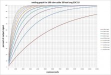
I've attached one graph, I had to copy it from another forum, as I can't find the orig at this moment...
Cheers, John
Attachments
I am well aware of the full correct expression. As well as the textbooks.
The textbooks actually need updating. edit: especially skin theory..quite a few of the beam/magnet physicists here have gotten into trouble using what is in the textbooks. The best one I know has NO textbooks. The reason: he derives all he needs from Maxwell's equations, that way he knows it's correct. (and sonufagun...he's always right..)
Hmm..
take a hot amplifier, a single driver 8 ohms, and let's build a constrained cable 10 meters long with a characteristic impedance of 8 ohms using a dielectric with a relative permittivity of 3.
I might ask what speaker cable with 220pF/ft would still make the amplifier oscillate with an 8 Ohm resistor instead of the speaker? I think I still have a 3' high Smith chart that we could work this out on (I realize this is a pretty nerdy joke).
I might ask what speaker cable with 220pF/ft would still make the amplifier oscillate with an 8 Ohm resistor instead of the speaker? I think I still have a 3' high Smith chart that we could work this out on (I realize this is a pretty nerdy joke).
It was over 7000 pf total. And that cable with an 8 ohm resistor will look like an 8 ohm load for all frequencies from DC to daylight. The amp sees NO capacitance or inductance.
Man, you are nerdy indeed...I never had one 3 feet tall...sheesh..was it taped to a wall in your bedroom???
Cheers, John
It was over 7000 pf total. And that cable with an 8 ohm resistor will look like an 8 ohm load for all frequencies from DC to daylight. The amp sees NO capacitance or inductance.
Man, you are nerdy indeed...I never had one 3 feet tall...sheesh..was it taped to a wall in your bedroom???
Cheers, John
Yes but a sufficiently long even slightly lossy line will always look like its characteristic impedance, so all you need is a few miles of it and it won't matter. It was a gift from a professor who knew Mr. and Mrs. Smith personally.
Yes but a sufficiently long even slightly lossy line will always look like its characteristic impedance, so all you need is a few miles of it and it won't matter.
You must have a big living room...🙂
I used 10 meters as the example. For some speaker systems, they fluctuate wildly across the audio band..they'd take the biggest hit settling-wise..
It was a gift from a professor who knew Mr. and Mrs. Smith personally.
Was that before or after they blew up their house?
Cheers, John
- Status
- Not open for further replies.
- Home
- Design & Build
- Parts
- Interconnect cables! Lies and myths!